background image

60

(COG), Distance To Go (DTG)
to waypoint, Bearing to way-
point, Time To Go (TTG) to
waypoint, and local time and
date displays at the bottom of
the screen.

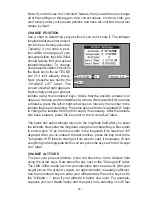
Your present position shows at
the top of the screen in latitude/
longitude coordinates. This is
shown in degrees, minutes, and
thousandths of a minute. For
example, on this page, the present position is 31 degrees, 8.655 minutes
north latitude and 82 degrees, 50.445 minutes west longitude.

Please note that you must recall a waypoint to use the Bearing, Distance
To Go, and Time To Go displays.

STEERING SCREEN
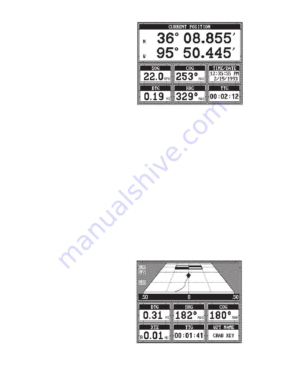
The steering screen shows a pictorial view of your boat and course
travelled. This is called a Course Deviation Indicator or CDI. It also shows
Distance To Go (DTG), Bearing to Waypoint (BRG), Route Name (RTE
Name), Cross Track Error (XTE), Time To Go to Waypoint (TTG), and
Waypoint Name (WPT Name). Press the MENU key, then press the key
next to the "Steer Screen" to view this display.

Your present position is shown by the arrow. The arrow shows the
direction the boat is heading relative to the waypoint. In theory, if you steer
the boat with the arrow always pointing towards the waypoint, then you will
arrive at the waypoint. The solid line extending from the arrow is your track
or path you’ve taken. To travel directly to a waypoint, try to keep the arrow
on the center line. The waypoint is depicted by a box at the top of the CDI
display. As you approach the
waypoint, the arrow and the
box will move closer together.
If you travel past the waypoint,
the waypoint’s box will move to
the bottom of the display.

The numbers on the top left
side of the screen are distance
markers, showing the remain-
ing distance to the recalled
waypoint. If the numbers have

Summary of Contents for LMS-350A

Page 1: ...INSTALLATION AND OPERATION INSTRUCTIONS LMS 350A ...

Page 2: ...ge of all available navigation tools when travelling to a waypoint but will also visually check to make certain a clear safe path to the waypoint is always available NOTICE As of this writing the Department of Defense DOD has not declared the GPS navigation system operational The system is still in a testing phase Satellites can be turned off or accuracy can be degraded at will by the system opera...

Page 3: ...4 SONAR FREQUENCY 25 DUAL FREQUENCY OPERATION 26 MENU PAGE 2 27 ADJUST BACK LIGHT LEVEL 27 BACK LIGHT ON OFF 27 SPEAKER VOLUME 27 TURN DIGITAL BOX OFF 28 CONSTRUCT DIGITAL BOX 28 MENU PAGE 3 29 DISPLAY ZOOM BAR 29 DISPLAY ZONE BAR 29 DIGITAL SONAR 30 TURN ALL SONAR OFF 30 CHART CURSOR 30 MENU PAGE 4 30 FASTRAK 31 SELECT UNITS OF MEASURE 31 CLEAR DISTANCE LOG 32 DEPTH LINES 32 MENU PAGE 5 33 ADJUST...

Page 4: ......

Page 5: ...ayandkeyboard are also lighted for night operation The LMS 350A also has digital depth boat speed surface water temperature and distance travelled log displays requires an optional ST T speed temperature sensor IfyoupurchaseandinstallaLGC 1GPSmodule theLMS 350Acanshow position and navigation information Utilizing Rockwell s NavCoreV technology this GPS receiver is second to none in it s class MOUN...

Page 6: ...M CLAMP TURNED UP BOLT Once you ve determined the location for the unit cut the hole according to the drawing shown above Measure carefully before cutting After cutting the dash place the gasket supplied with the LMS 350A around the unit and place the unit in the hole Supplied with the LMS 350A are rubber pads bolts washers and cam clamps to attach the LMS 350A to the dash Peel the adhesive backin...

Page 7: ...ossible For example if you have to extend the power cable to the battery or power buss attach one end of the fuse holder directly to the battery or power buss This will protect both the unit and the power cable in the event of a short The LMS 350A uses a 3 amp fuse IMPORTANT Do not use this product without a 3 amp fuse wired into the power cable Failure to use a 3 amp fuse will void your warranty ...

Page 8: ... the shield to the other device Use the green and black wires in the same manner to attach a DGPS recevier s output to the LMS 350 s input green wire See the other instrument s manual and the NMEA section in this manual for more information TRANSDUCER CONNECTIONS The LMS 350A has dual frequency capability It can operate at 50 or 192 kHz separately or at the same time The connection diagram below s...

Page 9: ...the antenna shouln t be the highest part of the boat Surface Mounting With Access If you have access underneath the mounting surface use the gasket supplied with the GPS module as a template Drill four 5 5 mm 7 32 holes and one 17 mm 11 16 hole for the module s cable Attach the cable to the module and pass it down through the hole in the gasket and the mounting surface Use 5 mm screws flat washers...

Page 10: ...ket and down the hole Place the module on the gasket Slide the cleats onto each end of the module and using the cleats as templates mark four holes for 5 mm 10 mounting screws Drill the holes then replace the cleats on the module and fasten them to the mounting surface with 5 mm 10 screws Route the cable to the LMS 350A 12345678901234567890123456789012123456789012345678901234 123456789012345678901...

Page 11: ...g adapter and align the four threaded holes in the module with the holes in the pole mounting adapter Using the four stainless steel 5 mm screws and lock washers supplied with the LMS 350A attach the pole mounting adapter to the GPS module This completes the assembly GPS MODULE SET SCREW POLE MOUNTING ADAPTER POLE GPS MODULE CABLE MOUNTING ADAPTER POLE POLE CABLE MOUNTING ADAPTER If the pole or ma...

Page 12: ... the keyboard activates the first menu page The keys along the bottom of the screen are used to switch between the sonar optional GPS and windows modes SONAR Press this key to switch to the sonar display GPS The GPS navigation displays show when you press this key PLOTTER Press this key to show the GPS Plotter display WINDOWS This key gives you access to the windows mode which lets you customize d...

Page 13: ... the lights will automatically turn themselves off The menus will also disappear after ten seconds or you can turn them off by pressing the CLR key on the left side of the zero 0 key The Metric label at the top of the screen works the same way Press the key adjacent to the Metric label to change the depth from feet to meters This also changes the temperature display to degrees Celsius speed to kno...

Page 14: ...the AUTO key brings up a menu letting you switch the unit into or out of the automatic mode A help label also appears on the screen Pressing the key adjacent to the help label gives you a description of how automatic works and how it affects different functions MENUS The LMS 350A uses menus extensively to guide you through the func tions and features of the unit The menu key accesses many of these...

Page 15: ... key Everyoneofthegroupscreens can be modified to some ex tent For example press the MENU key while group A is displayed Three new labels appear on the display as shown above Two of these labels are window menus Pressing the key adjacent to one of the window menu labels gives you a menu with functions that relate only to that window For example if you press the key adjacent to the window menu labe...

Page 16: ...o the NEXT label This changes the displayed window and description When you ve finished viewing the windows press the CLEAR key MODIFYING GROUPS To modify or customize a group first press the WIN DOWS key then press the MENU key Now press the key adjacent to the MAIN MENU labelatthebottomofthescreen The screen shown at right ap pears Now press the key adjacent to the RE PROGRAM A GROUP label The s...

Page 17: ...on t want to fill a screen and only use one two or three windows in a group simply press the key adjacent to the STOP label This saves the group and exits the modify windows mode Remember you can always return to the full screen sonar mode by pressing the SONAR key in the bottom left corner of the LMS 350A To switch back to your customized screen from the full screen sonar simply press the WINDOWS...

Page 18: ...ic mode you have a limited adjustment range on the Sensitivity control and no control over the Range Zoom adjusts differently in automatic than manual also SONAR OPERATION ToturnAutomaticoff firstpress the AUTO key A menu ap pears at the bottom of the screen above the left and right arrows Press the left arrow key to switch to the manual mode The letters Man ap pear in the upper left corner of the...

Page 19: ...edure to adjust it is the same whether the unit is in the automatic or manual mode To adjust the sensitivity press the SENS key The sensitivity adjust menu appears on the right side of the screen The sensitivity menu has left and right arrows plus a horizontal bar graph The graph gives a visual indication of the sensitivity level The number above the arrows also shows the percentage of sensitivity...

Page 20: ...lly any combina tion of upper and lower limits For example a range with a 15 foot upper limit and a 45 foot lower limit creates a 30 foot zoom window If the original range was zero to sixty feet then this created a 2X zoom To change the range first make certain the LMS 350A is in the manual mode Next press the RANGE key The range adjustment menu appears onthe rightsideofthedisplay Tochangeonlythel...

Page 21: ... either the CHANGE UPPER LIMIT or CHANGE LOWER LIMIT la bels On the screen shown at right the key next to the CHANGE UPPER LIMIT was pressed Nowenterthedesired depth using the numbered keys In this example we en tered 35 feet Now press the ENT key The LMS 350A erases the range menus from the screen and uses the new range you entered as shown below To change the lower limit sim ply repeat the above...

Page 22: ...ing it on the display at all times when the automatic feature is on Once you ve set the zoom as desired press the CLR key to erase the menus ZOOM MANUAL MODE When you press the zoom key while the unit is in the manual mode the screen shown below appears All of the menus on this screen work identically as described above However one additional menu item is shown when the unit is in the manual mode ...

Page 23: ...rd as you press the keys After you ve made the adjustment press theCLRkeytoerasethemenu To stop the chart press the key adjacent to the STOP label in the unit s lower left corner To start the chart press the key next to the START label GRAYLINE GRAYLINE lets you distinguish between strong and weak echoes It paints gray on targets that are stronger than a preset value This allows you to tell the di...

Page 24: ...eys are pressed The bar chart also gives a graphical indication of the GRAYLINE level You can see the change on the screen both on the menu and on the chart record as you press the keys After you ve made the adjustment press the CLR key to erase the menu FISH I D The Fish I D feature identifies targets that meet certain conditions as fish The micro computer analyses all echoes and eliminates surfa...

Page 25: ...ay see Fish I D symbols on the screen when actually there are no fish Practice with the unit in both the Fish I D mode and without to become more familiar with the Fish I D feature To turn the Fish I D feature on press the menu key then press the key adjacent to the Turn Fish ID On label Echoes will continue to scroll across the screen however the surface clutter at the top will no longer be displ...

Page 26: ...epth or GPS Alarms to adjust the shallow or deep digital alarms Press the key next to the Set Zone Alarm to adjust the zone alarm The fish alarm doesn t have an adjust ment It s either on or off Thefollowingsectiondescribes each sonar alarm and its limits FISH ALARM Use the fish alarm for a distinctive audible alarm when fish or other suspended objects are detected by the Fish I D feature A differ...

Page 27: ... The screen on the previous page appears Now press the key next to the Set Depth Alarms label The screen at the top of this page appears To adjust the shallow alarm press the key next to the Shallow label To adjust the deep alarm press the key next to the Deep label Both alarms adjustidentically We llusethe shallow alarm as an example Pressing the key next to the Shallow label moves the black box ...

Page 28: ...ve the bottom of the bar higher or lower To move the top of the bar first press the key next to the CHANGE TO UPPER la bel Now use the arrow keys to move the top of the bar higher or lower When you have the zone alarm bar set as desired press the CLR key to erase the menus The above steps automatically turn the zone alarm on if it was off To turn the zone alarm off press the MENU key then press th...

Page 29: ...re quency label The screen shown at left appears This menu lets you change the frequency of both the chart and the digital sonar Typically you should use the 192 kHz frequency in shallow water and the 50 kHz fre quency in deep water Now press the key adjacent to the desired frequency either 50 kHz 192 kHz or both 50 and 192 kHz split screen operation Note Only the chart can operate at both frequen...

Page 30: ...al Frequency Split Screen Mode Left chart is operating at 50 kHz right chart is 192 kHz sensitivity or the right arrow to increase it When you re fin ished press the CLR key to erase the menus Note If no frequency identification shows at the bottom of the screen then the 192 kHz frequency is in use The letters 50 kHz always show at the bottom of the screen when the 50 kHz frequency is in use Remem...

Page 31: ...djustable To change the volume press the MENU key then press the key adjacent to the More label Now press the key next to the Adjust Speaker Volume label A screen appears with the speaker volume adjust menu which is similar to the light adjust menu shown above A musical tune sounds to indicate the current speaker volume Now press the left arrow key to decrease the volume level Press the right arro...

Page 32: ...off as desired To select the digital displays menu first press the menu key then press the key next to the More label Next press the key adjacent to the CONSTRUCT DIGITAL INSTRUMENT BOX menu A screen appears that is similar to the one below Now press the key adjacent to the desired display For ex ample to turn the temperature display on press the key adja cent to the Include Tempera ture label Onc...

Page 33: ...ss the key next to the Dis play Zoom Bar label A screen similar to the one at left ap pears Note that turning the zoom bar on also turns the zoom feature on To turn the zoom bar off repeat the above steps until the third menu page appears then press the key adjacent to the Remove Zoom Bar label This removes the zoom bar but leaves the unit in the zoom mode See the zoom section for more information...

Page 34: ...ppears Now press the key adjacent to the Turn Digital Sonar Off label To turn it back on again repeat the same steps CHART CURSOR The LMS 350A has a chart cursor that lets you pinpoint a target s depth The cursor is simply a movable horizontal line that extends across the display from right to left A depth box at the far right end of the line shows the line s depth In the example at the top of the...

Page 35: ... adja cent to the Turn Chart Fastrak On label To turn it off repeat the same steps The TURN FASTRAK OFF label appears on this page when Fastrak is on Press the key next to this label to turn it off MENU PAGE 4 FASTRAK This feature converts all ech oes to short horizontal lines on the display s far right side The graphcontinuestooperatenor mally FASTRAK gives you a rapid update of conditions di rec...

Page 36: ... adjacent to the unit that you wish to change For example press the key next to the Depth label two times to switch from feet to meters This moves the black box two times from the FT to the M When you have the units of measure set as desired press the key next to the Exit label CLEAR DISTANCE LOG If the optional speed temperature sensor is attached to the LMS 350A it starts counting distance as so...

Page 37: ...TTER 60 foot range with maximum SCC surface clutter will be re duced down to 45 feet There are three levels of SCC availableontheLMS 350A low medium and high When it s turned on for the first time the SCC level is low To change it presstheMENUkey thenpress the key next to the More label until the fifth menu page ap pears Now press the key adja cent to the Surface Clarity label until the black box ...

Page 38: ...f you are having trouble with noise we suggest that you take steps to find the interference source and fix it rather than continually using the unit with the high ASP setting However there are times when you may want to turn the ASP feature off This allows you to view all incoming echoes before they are processed by the ASP feature To change the ASP level press the MENU key then press the key next...

Page 39: ... water depth from thefaceofthetransducer there can be a significant difference between the actual water depth and what is displayed on the unit For example suppose you mount a bolt thru hull trans ducer on the bottom of the boat When you launch the boat you find that this location places the transducer three feet below the surface of the water Therefore the depth sounder always reads three feet sh...

Page 40: ...r to add tenths For ex ample to set the keel offset to three feet first press the 3 then press the 0 key Finally press the ENT key To enter a negative keel offset use the same steps as above but press the key next to the Keel label To turn the keel offset feature off enter 0 0 or press the CLR key When you have the keel offset at the desired setting press the key next to the Exit label The unit re...

Page 41: ...dometer calibrated press the key next to the Exit label to return to the sonar screen BATTERY BACKUP The LMS 350A saves all system settings such as windows units of measure alarm settings and more in memory that is powered by an internal battery This keeps the memory alive while the unit is turned off The LMS 350A gives you the ability to turn this battery on or off Turning it off causes the LMS 3...

Page 42: ...ypically wide cone angle transducers 20 degrees are ideal for operating in shallow to medium water depths The 20 degree cone angle allows you to see more of the underwater world In 15 feet of water the 20 degree cone covers an area about six feet across The 8 degree transducer covers only about a two foot circle The 20 degree transducer is almost always the best to use in fresh water the 8 degree ...

Page 43: ...one passes over a fish in shallow water the signal displayed on the LMS 350A may not arch at all This is due to the narrow cone diameter and the resolution limitations of the display FISH ARCHES Fish arches are created when the cone of sound passes over a fish The distance to a fish when the cone first strikes it is shown as A on the next page When the center of the cone strikes the fish the dista...

Page 44: ...creasing the sensitivity areas where fish are likely to be Even if it s the first time on the water IMPORTANT SERVICE INFORMATION If your unit is not working or if you need technical help please use the following troubleshooting section before contacting the factory customer service department It may save you the trouble of returning your unit Unit won t turn on 1 Check the power cable s connectio...

Page 45: ...sonar s ability to find the bottom If the sonar can t find the bottom signal while it s in the automatic mode the digital will flash continuously It may change the range to limits far greater than the water you are in If this happens place the unit in the manual mode then change the range to a realistic one for example 0 100 feet and increase the sensitivity As you move into shallower water a bott...

Page 46: ...tionless fish stay in the cone showing on the display as straight horizontal lines NOISE A major cause of sonar problems is electrical noise This usually appears onthesonar sdisplayasrandompatternsofdotsorlines Inseverecases it can completely cover the screen with black dots or cause the unit operate erraticly or not at all To eliminate or minimize the effects of electrical noise first try to dete...

Page 47: ...alternator filters or routing the sonar unit s power cable away from engine wiring Again routing the power cable directly to the battery helps eliminate noise problems Make certain to use the in line fuse supplied with the unit when wiring the power cable to the battery When no noise appears on the sonar unit after all of the above tests then the noise source is probably cavitation Many novices or...

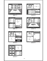
Page 48: ...pages To view these groups simply press the WINDOWS key then re peated press the down arrow key This will cycle the unit through all groups Remember the optional LGC 1 GPS module must be connected to the unit for the navigation features to work GROUP E GROUP D GROUP G GROUP F GROUP C GROUP B GROUP A ...

Page 49: ...45 GROUP H GROUP I GROUP M GROUP L GROUP O GROUP N GROUP K GROUP J ...

Page 50: ...46 GROUP P GROUP Q GROUP U GROUP T GROUP V GROUP S GROUP R ...

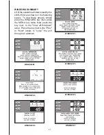
Page 51: ...ng pages To view these groups simply press the WINDOWS key then press the MENU key twice Now press the key next to the View all Windows label Press the key next to the Prev or Next labels to cycle the unit through all windows WINDOW 5 WINDOW 4 WINDOW 7 WINDOW 6 WINDOW 3 WINDOW 2 WINDOW 1 ...

Page 52: ...48 WINDOW 13 WINDOW 12 WINDOW 15 WINDOW 14 WINDOW 11 WINDOW 10 WINDOW 9 WINDOW 8 ...

Page 53: ...49 WINDOW 21 WINDOW 20 WINDOW 19 WINDOW 18 WINDOW 17 WINDOW 16 ...

Page 54: ...e the prudent navigator will not only take advantage of all available navigation tools when travelling to a waypoint but will also visually check to make certain a clear safe path to the waypoint is always available NOTICE As of this writing the Department of Defense DOD has not declared the GPS navigation system operational The system is still in a testing phase Satellites can be turned off or ac...

Page 55: ...DATE 67 GRID LINES 67 SELECT UNITS OF MEASURE 68 EVENT MARKER 69 USING THE EVENT MARKER WITH THE CURSOR 69 ERASING ICONS 70 WAYPOINT NAVIGATION 70 HOW TO SAVE A WAYPOINT 71 QUICK SAVE METHOD 71 VIEW AND SAVE METHOD 71 ENTER NEW WAYPOINT 72 NAME A WAYPOINT 72 ERASE A WAYPOINT 73 RECALL A WAYPOINT 73 ROUTES 74 CREATING A ROUTE 74 NAME A ROUTE 75 WAYPOINT SELECTION 75 FOLLOWING A ROUTE 76 CANCEL NAVI...

Page 56: ...y The GPS receiver requires at least three satellites to give a 2D fix A 2D fix is your position inlatitude longitude A3Dfixisyourlatitude longitudeplusaltitude When it locks on to at least four satellites it displays a 3D fix As the receiver locks on to each satellite it calculates the distance from the satellite by measuring the length of time it takes the radio signal to reach it Each satellite...

Page 57: ...n 100 meters Of course accuracy also depends on the angle of the satellite above the horizon signal to noise ratio the number of satellites tracked at one time the more the better and other factors The smallest ranges on the plotter may not be usable if the SA is high The present position symbol can move off the screen even while you re sitting still Don t let this discourage you however GPS by na...

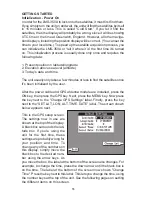
Page 58: ...ess to find the satellites once it s been initialized by the user After the power cable and GPS antenna module are installed press the ON key then press the GPS key Next press the MENU key Now press the key next to the Change GPS Settings label Finally press the key next to the SET LAT LON ALT TIME DATE label The screen shown below appears next This is the GPS setup screen The settings now in use ...

Page 59: ...itude that needs changing Press the key next to the Latitude N S label to change the latitude from north to south if necessary After the latitude has been entered press the key next to the Accept Lat label The black box automatically moves to the longitude field after you enter the latitude Now enter the longitude using the numbered keys Be certain to enter a zero 0 as the first number in the long...

Page 60: ...ime label when you re finished CHANGE DATE To enter today s date press the arrow keys to move the black box to the Local Date field Now press the key next to the Change Date label Use the number keys to enter the date Press the key next to the Accept Date label when you re finished The numbers at the top of the screen should be correct If they aren t press the key next to the label that you need t...

Page 61: ...llite information screen These displays were designed to show the most important data However you can customize all of them to some extent through the Change Display feature on the first GPS menu screen There are other screens that can be customized by using the Windows feature See the Windows section for more detail To customize these screens see the Customize section IMPORTANT If the data shown ...

Page 62: ...r the VISIBLE SATS heading In the upper right corner of the screen are the DOPS displays These show you the Dilution Of Precision DOP for the horizontal HDOP geomet ric GDOP position PDOP time TDOP and vertical VDOP The GDOP is the combination value of HDOP VDOP and TDOP The smaller the GDOP s number is the better The GPS receiver selects satellites based on GDOP therefore it always tries to use s...

Page 63: ...Name RTE Name Cross Track Error XTE Time To Go to Waypoint TTG and Waypoint Name WPT Name Press the MENU key then press the key next to the Steer Screen to view this display Your present position is shown by the arrow The arrow shows the direction the boat is heading relative to the waypoint In theory if you steer the boat with the arrow always pointing towards the waypoint then you will arrive at...

Page 64: ...raphical display at the top let you accurately steer the boat to a waypoint CUSTOMIZE SCREENS The digital displays on the bottom half of the Position Steering and Satellite screens plus the displays on the Plotter screen can be changed as desired To show how this is done we ll use the Position screen as an example To customize the Position Screen first make certain it is showing by pressing the GP...

Page 65: ... Time and Date COG Course Over Ground VMG Velocity Made Good DEPTH Water Depth When you have the display arranged as desired press the CLR key This locks the display Every time you switch to this display it will appear as you designed it unless you preset the unit PLOTTER The plotter lets you see your course and direction of travel on the screen If you ve recalled a waypoint the plotter shows your...

Page 66: ...eSpeed Over Ground SOG Distance To Go DTG and Bearing BRG digital displays All of these displays are used only when a waypoint is recalled except COG and Positioin which are always active These displays also can be customized See the Plotter Menus section for more detail PLOTTER CURSOR The plotter cursor can help you determine the latitude longitude of a waypoint or event marker To use it press th...

Page 67: ...ypoint The number inside the flag is the recalled waypoint number In this example waypoint number 10 is the destination The dotted line is the shortest most direct course from the starting point to the destination Follow this line to get to the waypoint The arrival alarm is automatically set to sound a tone when you come within a preset distance to the destination when you recall a waypoint See th...

Page 68: ...oint icons also ALARMS Press this key for the alarms menu For more information on the alarms see the ALARMS section CHANGE PLOTTER DISPLAY When the LMS 350A is first turned on or after a preset the plotter screen hasacolumnofdigitaldisplaysonthe left side of the screen These displays can be changed or erased completely This gives you a full screen plotter To change the plotter display press the ME...

Page 69: ...on shown by the cross hairs This automatically turns the arrival alarm on also The unit returns to the plotter screen with a black box around the position display at the top of the screen as shown below The word POSITION also flashes identifying it as ready for change Press the left or right arrow keys to change the data displayed in that box For example to change the Posi tion display to Distance...

Page 70: ...rawing a solid line behind your present position The track is updated once every instantly when the unit is turned on for the first time However if you re travelling a long distance the track line may end prematurely due to the limited number of dots available that plot the track Using a longer update time To change the update rate press the MENU key while the unit is in the plotter mode then pres...

Page 71: ...mea sure are in statute miles for distance miles per hour for velocity degrees magnetic for bearing altitude in feet and time is in the 12 hour format a m p m Press the key next to the unit that you wish to change For example press the key next to the Distance label twice to switch from miles to kilometers This moves the black box two times from the MI to the KM When you have the units of measure ...

Page 72: ...con always stays in this location It s saved in memory so it will always show on the display even if the unit is turned off and on again Note When you place an icon first make certain the icons are on When the LMS 350A is first turned on or after a preset the icons are automati cally turned on However if you turn the icons off using the Set Icons feature on the first plotter menu screen then the i...

Page 73: ...he key next to the DELETE ICON BANK label The screen shown above appears Now select the group of icons that you wish to erase by pressing the key next to the desired icon After pressing the key the LMS 350A erases all of the selected icons from the plotter HOW TO SAVE A WAYPOINT Waypointsarelocationsontheearth ssurfacethatyouwishtogoorreturn to Waypoints are useful for marking shipwrecks hot fishi...

Page 74: ...ber in the list appears at the top of the page This is the number that your present position will be stored under Your position at the time you pressed the WAYPT key is shown in the Current Position box in the middle of the screen If you wish to save the location in the Current Position box under this waypointnumber simplypress the key next to the Use Cur rent Position label The position shown in ...

Page 75: ...e entered the latitude press the key next to the Accept Lat label The waypoint save menu reappears Next using the arrow keys move the black box to the longitude position and press the key next to the Change Lon label Now enter the longitude Make certain to add a zero to the longitude if it s less than 100 degrees Forexample ifthelongitudeis85degrees thenenter 085 Pressthekey next to the Longitude ...

Page 76: ...e Waypoint Erase feature lets you erase waypoints from the list To erase a waypoint firstpresstheWAYPTkey then press the key next to the WPT Save label Now press the key next to the Increase WPT or Decrease WPT label until the desired waypoint number ap pears on the screen Simply press the key next to the ERASE WPT label The screen shown above appears A message appears on the screen that says WAIT...

Page 77: ...ormation is shown to this waypoint and the process repeats When you reach the last waypoint in a route the arrival alarm sounds until you turn it off There are four steps required to create and follow a route First you must create and name the route Next select the waypoints used in the route Then determine the starting waypoint Next tell the unit to follow the route Finally the unit will ask you ...

Page 78: ...e the black box to the next letter position Now press the RANGE key The letter E appears on the screen Use the number keys to enter numbers Repeat this process until the entire name has been written on the screen Now press the key next to the Accept Name label The LMS 350A returns to the route menu You can now enter the waypoints used in the route Waypoint Selection If you ve named a route the bla...

Page 79: ... are shown beneath the route number and name If you wish to recall a different route press the key next to the In crease RTE or Decrease RTE label to cycle through the available routes After you ve selected the de siredroute you llnoticeablack box surrounding the first way point in the route This is the starting waypoint box If you wish to start the route using the first waypoint in the route simp...

Page 80: ...ting of waypoints number 1 2 and 3 and you wish to changewaypointnumber3towaypointnumber5 SimplypresstheMENU key then press the key next to the More label then press the key next to the Save Edit Route label Using the keys next to the Increase or Decrease RTE labels se lect the route number that you wish to change The list of waypoints used in the route are shown beneath the route num ber and name...

Page 81: ... key next to the Alarms label The screen shown at right appears Now press the key next to the desired alarm s label In this example the Arrival alarm is set Pressing the key moves the black box from OFF to Adjust A new box appears at the bottom of the screen as shown at the bottom of this page Using the numbered keys enter the desired alarm trip distance In this example we re setting the arrival a...

Page 82: ...1 to 9 9 miles CHANGING GPS SETTINGS For the fastest acquisition of satellites the LMS 350A must be initialized when it s turned on for the first time This is described at the beginning of the GPS section in this manual However if you need to change only one of the parameters such as time use the menu features in the CHANGE SETUP menu To do this press the MENU key then press the key next to the Ch...

Page 83: ...ceiver This gives the unit much better accuracy than normal However before purchasing and installing a beacon receiver make certain there are transmitters in the area you wish to use Presently the LMS 350A can use the Magnavox MX 50R or StarLink MRB 2A Please note that the LMS 350A doesn t send NMEA 0183 data when the Magnavox MX 50R beacon receiver is activated NMEA SETUP Once you connect the wir...

Page 84: ...ation frequency orthe DECFREQ todecrease it Do the same for the bit rate Note If you set the frequency to zero the Starlink MRB 2A will automatically change fre quencies and bit rates for new stations as you travel Otherwise you will have to manually change the frequency and bit rate when you move out of range of the current station When the station frequency and bit rate are adjusted to their pro...

Page 85: ...lay navigation information in magnetic or true When it s turned on for the first time magnetic is used To switch to true press the MENU key while a GPS screen is displayed Next press the key next to the Change GPS Settings label Now press the key next to the Select Units of Measure label Now simply press the key next to the Bearing label This moves the black box from MAG to TRU Press the key next ...

Page 86: ...neath the position is the time that you pressed the Man Overboard key At the bottom of the screen are the navigation data displays showing the Distance DTG Bearing BRG Course COG Speed Over Ground SOG and Time To Go TTG back to the postion at the top of the display Using these displays along with the plotter in the lower right corner of the screen gives you the information you need to steer back t...

Page 87: ...y saves the position the first time the Man Overboard key is pressed To save a new Man Overboardpostion youmustfirstcleartheoldpositionbypressingthekey adjacent to the DISABLE MOB label You can navigate to a waypoint using the Waypoint Recall feature however when you go back to the Man Overboard screen the AccuNavII stops navigating to the recalled waypoint and show navigation data to the Man Over...

Page 88: ...the Exit label GPS SIMULATOR Thisfeatureplacespositionand navigation data on all screens including the plotter The unit navigates a closed course It shows bearing and distance to go course over ground and other information A recurring message appears alerting you that the simulator mode is en abled Don t navigate when the simulator is on To turn the simulator on press the MENU key then press the k...

Page 89: ...osition that is 010 degrees less than the one on the chart Using the Position Correction Factor PCF Offset feature you make the unit read the same as the chart If you raise anchor and move the unit will continuously add the change to all position displays This makes it more closely match the datum used by the chart For this reason you should be careful when entering the PCF offset This offset is s...

Page 90: ...bythechart In other words our position shown on the unit is 0 012 minutes north and 0 068 minutes east of the position shown on the chart After you ve entered the desired offset press the key next to the PCF Offset OFF ON label This turns the PCF correction factor that you entered on To leave this screen press the key next to the Exit label This also puts your changes into effect To turn these cha...

Page 91: ...aximum accuracy achievable with Standard Positioning Service Position 25 meters CEP Velocity 0 25 meters sec RMS Without SA PDOP 6 0 NMEA 0183 SENTENCES RMB Minimum Recommended Sentence Part B RMC Minimum Recommended Sentence Part C GLL Present Position Latitude Longitude APB Autopilot Steering Data DBT Water Depth MTW Water Temperature oC VHW Speed Through Water KPH VLW Distance Travelled LOG NM ...

Page 92: ...89 This page intentionally left blank ...

Page 93: ...90 LITHO IN U S A 988 0133 01 ...

Reviews: