background image

2

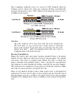
The remaining auxiliary wires are used for DSC (Digital Selective
Calling) service, where the radio can exchange latitude and longitude
position information with a GPS (Global Positioning System) receiver
in NMEA 0183 format.

Wiring to transmit NMEA information

to a GPS receiver.

Wiring to receive NMEA position information

from a GPS receiver.

Caution

All of the auxiliary wires have bare ends for easier installation.
The bare ends on any unused wires could cause an electrical
short if left exposed. To prevent this, you should cover the indi-
vidual wire ends – either by capping them with wire nuts or
wrapping them with electrical tape.

Bracket Installation

Mount the unit in any convenient location, provided there is clearance
behind the unit when it's tilted for the best viewing angle. You should
also make sure there is enough room behind the unit to attach the
power, antenna and auxiliary cables. Pick a location far enough from
any compass to avoid compass deviation caused by the speaker magnet.
The radio must be installed at least three feet from the antenna. Make
sure there is space nearby to hang the mic clip.

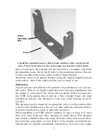
Holes in the gimbal bracket's base allow wood screw or through-bolt
mounting. You may need to place a piece of plywood on the back side of
thin fiberglass panels to reinforce the panel and secure the mounting
hardware. We suggest that you use stainless steel screws for installa-
tion.

Ground – (Red)

To Radio

To GPS unit

NMEA R (Brown)

Shield (Ground)

R

NMEA Tr (Orange)

Shield – (Ground)

 Ground – (Yellow)

To GPS unit

To Radio

Tr

Summary of Contents for LVR-850

Page 1: ...Pub 988 0158 001 www lowrance com LVR 850 DSC VHF Marine Radio Installation and Operation Instructions LVR 850 ...

Page 2: ...manual is strictly prohibited Lowrance Electronics may find it necessary to change or end our policies regulations and special offers at any time We reserve the right to do so without notice All features and specifications subject to change without notice All screens in this manual are simulated For free owner s manuals and the most current information on this product its operation and accessories...

Page 3: ...SCN Scan 6 MEM Memory 7 CALL 7 DISTRESS 7 Arrow Keys 7 PTT Press to Talk 7 DSC Calling vs non DSC Calling 7 What is a DSC call 7 How DSC works 8 Simplex or Duplex 8 MMSI Maritime Mobile Service Identity 8 MMSI Setup 9 Choosing a Channel 10 Making a Call 10 Receiving a Call 11 Section 3 Advanced Operation 13 Calls 13 Transmission 13 AllShips Call 13 Directory Call 14 Distress Call 14 Last Call 16 N...

Page 4: ...band radio telephone or marine satellite terminal must have an FCC license License application forms for ship and land stations can be downloaded free from the FCC web site at this address www fcc gov formpage html You may also order copies of these forms by calling the FCC Forms Dis tribution Center at 1 800 418 3676 At this time the FCC does not require recreational boaters to have a ship radio ...

Page 5: ...ro tection against harmful interference in a residential installation This equipment generates uses and can radiate radio frequency energy and if not installed and used in accordance with the in structions may cause harmful interference to radio communica tions However there is no guarantee that interference will not occur in a particular installation If this equipment does cause harmful interfere...

Page 6: ...F exposure limits Antenna types suited for this radio are described in the installation section DO NOT transmit for more than 50 of the total radio use time Transmitting more than 50 of the time can cause FCC RF exposure compliance requirements to be exceeded The radio is transmitting when the TX indicator is displayed on the screen You can cause the radio to transmit by pressing the PTT Push To T...

Page 7: ...t it To jump to MMSI setup flip to page 8 To acquire a free MMSI number see the web address on the bottom of page ii The third section Advanced Radio Operation offers more detailed in formation about the radio s features The section will touch on all as pects of the radio s functionality providing clear and complete explana tions via a convenient alphabetical layout Let s get started Powering Your...

Page 8: ...y convenient location provided there is clearance behind the unit when it s tilted for the best viewing angle You should also make sure there is enough room behind the unit to attach the power antenna and auxiliary cables Pick a location far enough from any compass to avoid compass deviation caused by the speaker magnet The radio must be installed at least three feet from the antenna Make sure the...

Page 9: ...nstallation but the higher it is mounted the better the reception That s because ma rine VHF radio signals travel only on a line of sight basis An ideal installation will give the antenna a clear view of the horizon in all di rections The antenna may be mounted on a gunwale rail or on flat surfaces like a deck roof or bulkhead In the case of some sailboats and powerboats it may be attached to a ma...

Page 10: ...ere it is separated from people by at least 3 feet of space How to Make a Distress Call Speak slowly clearly and calmly 1 Select VHF Channel 16 2 Press microphone button MAYDAY MAYDAY MAYDAY 3 THIS IS your ship ID 4 MAYDAY your ship name 5 Tell where you are what navigational aids or landmarks are near 6 State the nature of your distress 7 Give number of persons aboard and condition of any injured...

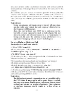
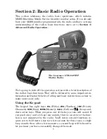
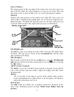
Page 11: ... in formation on Digital Selective Calling and basic instructions on how to make and receive calls Using the Keypad The keypad has eight keys H L Hi Lo WX Weather 16 9 Priority Channels SCN Scan MEM Memory CALL Call and the up and down arrow keys When you press any of the keys a tone will sound If you push a key and a 3 beep tone sounds there is an error or the func tion is not supported by the ra...

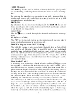
Page 12: ...tt If the LO ANNUNCIATOR is off the radio will transmit at 25 Watts WX Weather Dark clouds on the horizon Press the WX key to enter the WX WEATHER MODE and get the latest weather information Use the keys to change the WX channel 16 9 Priority Channel The 16 9 key is used to switch between priority channels It also allows you to exit various operation modes ignore incoming calls and cancel outgoing...

Page 13: ...a working channel set aside for the desired communication type Once they have left Ch 16 and the selected working channel is clear the individual hails the vessel again to initi ate communication What is a DSC call A relatively new technology digital selective calling DSC gives you the capability to dial another boat directly via the vessel s MMSI Mari time Mobile Service Identity number which fun...

Page 14: ...ll is the ability to place an individual call directly to another vessel Simplex or Duplex References to simplex and duplex channels are scattered throughout this manual Simplex channels transmit and receive messages on the same frequency Like a CB radio only one message can be transmitted at a time A duplex channel transmits and receives messages on differ ent frequencies Like a telephone it give...

Page 15: ...NCIATOR will blink and a large 0 will be displayed alongside a small 16 The big number 0 is the MMSI digit you are entering and the small digit 16 is the first MMSI character field position For example a small digit 2 rep resents the 2nd number from the left in your assigned MMSI If the number was 4 it would mean the big digit you were entering was the 4th number from the left and so on This examp...

Page 16: ...ou are ready to make a DSC call Choosing a Channel Before making a call to another vessel check the VHF chart in the back of this manual You ll have to choose a simplex communication channel authorized for the type of communication you desire Making a Call The LVR 850 supports five DSC call types ALLSHIPS CALL DIRECTORY CALL LAST CALL NEW CALL and DISTRESS CALL The example below details a NEW CALL...

Page 17: ... communication channel 2 Tune your radio to Ch 16 or Ch 9 Speak slowly and clearly stating the name of the vessel you are trying to contact followed by this is your ship name and call sign 3 When the other vessel responds say go to the desired channel num ber over 4 Switch to the other working channel After you are sure it is clear call out to the other vessel stating the vessel s name followed by...

Page 18: ...e number s directory location is shown If no match is made the ID ANNUNCIATOR blinks If you want to respond to the calling vessel just press the PTT button on the microphone Press the 16 9 key to ignore the call See page 18 to get more detailed information on call reception ...

Page 19: ...laces a call to any ship in range of you 2 Directory Call dials number from MMSI directory 3 Distress Call executes an emergency call to Coast Guard and other ships in range of you 3 Last Call dials last incoming call 4 New Call places call to caller not in the MMSI directory Press CALL then use the keys to scroll through the four choices DISTRESS CALL is a separate function so it is not included ...

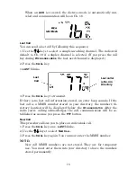
Page 20: ...call 5 Press the CALL key to transmit The called radio will acknowledge and a communication link will be established Just press PTT to talk In the following example Ch 8 was used to call a MMSI stored in di rectory No 3 When the ACK ANNUNCIATOR turns on the calling channel has been tuned in and a communication link established Press PTT to talk Distress Call In an emergency situation lift the red ...

Page 21: ...ll will be sent out The DSC Distress message is transmitted at 25 watts The Distress message contains your MMSI your position and the UTC time acquired from your GPS if you re using a GPS unit The DISTRESS ANNUNCIATOR is displayed during the transmission A loud 2 tone alarm sounds This alarm cannot be stopped unless the mode is canceled Pressing the 16 9 or PTT key cancels the DISTRESS WAITING MOD...

Page 22: ... stored an error beep sounds If the last call is a MMSI number stored in your directory the number s di rectory location will be displayed below the ID ANNUNCIATOR After the radio you re calling acknowledges the call communication will be es tablished as soon as you press the PTT button New Call This procedure allows you to place an individual call 1 Press the CALL key once LAST blinks 2 Use the k...

Page 23: ... just turn off the radio After you are satisfied with the new MMSI number press the call key 5 Press the CALL key and the radio will transmit the request If there is no acknowledgement ACK after 4 seconds the radio transmits the call again The radio will stay in standby mode indicated by the flash ing ID Annunciator until an ACK is received If an ACK is not received you can press the call key agai...

Page 24: ...ntact the calling vessel just press the PTT button Receiving an AllShips call Distress Call The reception of a DISTRESS CALL automatically sets the receiving radio s channel to Ch 16 Press the 16 9 key to turn off the distress alarm NOTE The LVR 850 does not respond to two types of DSC Distress calls 1 Distress relay from an intermediary vessel 2 Distress relay acknowledgment ACK from a coastal st...

Page 25: ...r proper usage and understanding In the US and Canada WX Weather channels are available WX channels are not available for international use An A ANNUNCIATOR will be displayed when an alternate channel is used That is telling you the radio is tuned to a simplex channel and normal ship to ship communication is appropriate If the A ANNUNCIATOR is off the radio is operating in duplex mode Channel Bank...

Page 26: ... MMSI input screen 5 Press the keys to enter the MMSI digits After entering the first MMSI digit press the MEM key to enter the second number The big digit again starts at 0 and the small digit now displays 2 The small number will increase each time you add a MMSI digit Use the keys to set the second MMSI digit and touch the MEM key to store Repeat the operation until all 9 digits have been entere...

Page 27: ...ure the DSC Monitor mode is on hold down the CALL key for 5 seconds to toggle the DSC Monitor mode off and on It must be on for your radio to receive a DSC call The DSC MON ANNUNCIATOR will be dis played onscreen if Ch 70 is being accessed Since there is no independ ent Ch 70 receiver the radio normally monitors Ch 70 and checks other channels on a regular basis to detect a squelch break This meth...

Page 28: ...NUNCIATOR is blinking the GPS data is not valid H L The H L key gives you control over the radio s wattage The high end is 25 Watts The low end is 1 Watt If the LO ANNUNCIATOR is off the radio will transmit at 25 Watts Some channels do not accept transmissions or are restricted to a 1 Watt level If you come across one of those chan nels and you try to switch to 25W you will hear a 3 tone error bee...

Page 29: ... turning on the radio This clears all memory channels with the exception of the Priority Channel Position Send Request Transmission Your radio can send and receive information on location if it is con nected to a GPS unit This will allow you to locate a vessel without transmitting messages back and forth To send your position P1 1 Press the CALL key then use the keys to select DIR from the main sc...

Page 30: ...r five seconds The screen will show FL P2 letting you know the MMSI is now stored in the P2 location The MMSI number will be stored in the P2 location until you edit or replace the MMSI in formation 3 Press the CALL key and the big digit will blink and the channel will be switched to Ch 16 Press the CALL key again and the position data will be requested through Ch 70 After the transmission on Ch 7...

Page 31: ...16 9 key for a few seconds until the priority channel switches to the other channel This is particularly useful when you want to make a non DSC call and Ch 16 is receiving a lot of transmission traffic The 16 9 key also allows you to exit various opera tion modes ignore incoming calls and cancel outgoing calls With a quick press of the 16 9 key the priority channel immediately is selected with hig...

Page 32: ...ry scan list press the MEM key then push the SCN key If you are in a different scanning mode you must stop the scan before switching to a MEMORY SCAN In that case press SCN MEM SCN To add channels to the memory scan list use the keys to tune in each of the channels you want to monitor As you tune in each channel depress MEM for three seconds to add it to the memory list The MEM Annunciator will ap...

Page 33: ...t used Wx channel always appears first Use the keys to change the WX channel In PRIORITY SCAN or MEMORY SCAN MODES pressing the WX key allows the WX ALERT function to be toggled off and on Select the WX channel before starting a PRIORITY SCAN or MEMORY SCAN If a WX ALERT a 1050Hz tone burst transmitted from the NOAA Weather service is issued a special circuit in the radio detects the tone and duri...

Page 34: ...ion Ship movement 08 X X X S 156 400 Commercial Intership only 09 X X X S 156 450 Boater calling channel Commercial and noncom mercial Recreational 10 X X X S 156 500 Commercial 11 X X X S 156 550 Commercial VTS in selected areas 12 X X X S 156 600 Port operation VTS in selected areas 13 X X X S 156 650 Intership navigation safety bridge to bridge 1 W 14 X X X S 156 700 Port operation VTS in selec...

Page 35: ...ation Ship movement 62A X S 156 125 Pacific coast Coast Guard East coast Commercial fishing only 62 X D 156 125 160 725 Public Correspondence Marine Operator Port op eration Ship movement 63A X X S 156 175 Port operation and commercial VTS in selected ar eas 63 X D 156 175 160 775 Public Correspondence Marine Operator Port op eration Ship movement 64A X X S 156 225 U S Government only Canada Comme...

Page 36: ...ine Operator 85 X X X D 157 275 161 875 Public Correspondence Marine Operator 86 X X X D 157 325 161 925 Public Correspondence Marine Operator 87 X X X D 157 375 161 975 Public Correspondence Marine Operator 88A X S 157 425 Commercial Intership only 88 X X D 157 425 162 025 Public Correspondence Ship to coast Hold down H L key while pressing PTT for 25W transmit ting power on these special marine ...

Page 37: ...MENT OR REFUND AS JUST DESCRIBED IS THE EXCLUSIVE REMEDY AVAILABLE TO YOU AGAINST US FOR ANY DEFECT MALFUNCTION OR NON CONFORMITY CONCERNING THE PRODUCT OR FOR ANY LOSS OR DAMAGE RESULTING FROM ANY OTHER CAUSE WHATSOEVER WE WILL NOT UNDER ANY CIRCUMSTANCES BE LIABLE TO ANYONE FOR ANY SPECIAL CONSEQUENTIAL INCIDENTAL OR OTHER INDIRECT DAMAGE OF ANY KIND Some states do not allow the exclusion or lim...

Page 38: ...ations and special offers at any time We reserve the right to do so without notice in Canada If you re in Canada and you have technical return or repair questions please con tact the Factory Customer Service Department Before any product can be re turned you must call customer service to determine if a return is necessary Many times customer service can resolve your problem over the phone without ...

Page 39: ...placement you must first receive a return authorization number from Customer Service Products shipped without a return authorization will not be accepted When shipping we recommend you do the following 1 Please do not ship the knobs or mounting bracket with your unit 2 If you are sending a check for repair please place your check in an envelope and tape it to the unit 3 For proper testing include ...

Page 40: ...Visit our web site Lowrance Pub 988 0158 001 Copyright 2005 All Rights Reserved Printed in USA 030305 Lowrance Electronics Inc ...

Reviews: