Screen Lift 750 Trolley Mount
7
5. Additional Assembly Instructions for Flatpack
Please read in conjunction with the instructions included
Please note that the spindles on the vertical legs are covered with rubber protectors
which need removing.
Remove the protective electrical tape on the limit switch on the end of the motor box.
It may also be necessary to remove the gold temporary clips from the vertical legs
earlier than shown in the instructions so that the spindle can be rotated to engage in
the sockets of the motor unit.
When fitting the rear handle this will need to be attached in the
top set of holes
with
the 8 button head Allen screws and not the middle set as shown on the instructions.
It is probably easiest to loosely attach this handle until the castor base has been fitted
and then to tighten the handle bolts at the end.
6. Fitting Mount Brackets to Screen
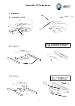
1. Remove the vertical plasma brackets from the front of the Screen Lift
trolley by undoing the securing clips shown in picture 2 and lit off.
Fix the brackets onto the rear of the plasma using the bolts provided.
The brackets bolt through one of the holes at the top of the bracket and
also through the slot.
2. Attach the two horizontal mounting rails to the front of the lift, using
the M6 x 12 fixings.
The top rail should have the threaded inserts at the top.
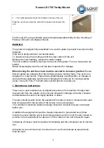
Hang the plasma onto both rails of the Screen Lift. Ensure the vertical
mounting bracket is secured to the top rail using the security clips and
the M6 button head screws as shown. This will ensure that the plasma
screen cannot be dislodged accidentally.
Check when the screen is installed that there is sufficient clearance
under the screen not to form a trap when the screen is in its fully
lowered position.


