L-Proxy User Manual
130
LOYTEC
Version 3.1
LOYTEC electronics GmbH
•
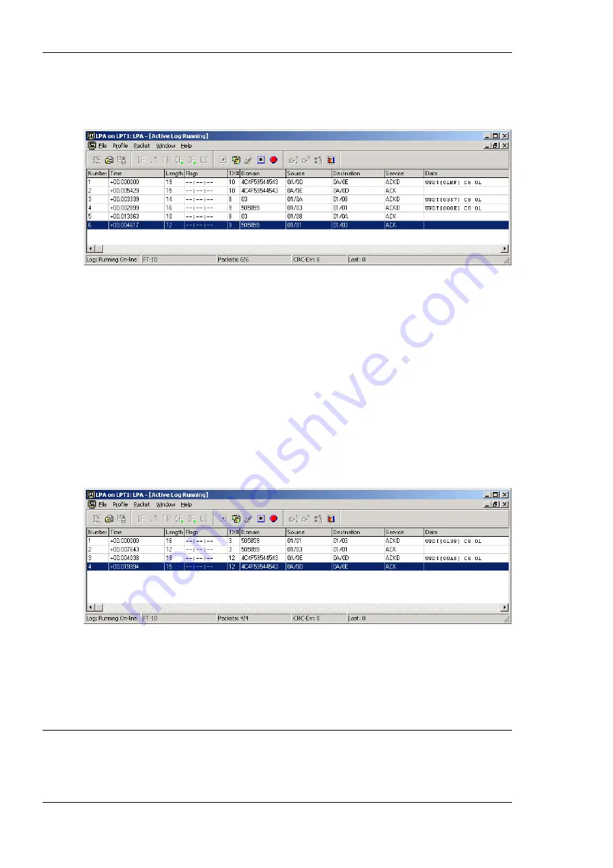
Packet #5: Node 7 sends an acknowledgement back to L-Proxy Port 3.
•
Packet #6: Node 8 sends an acknowledgement back to L-Proxy Port 4.
Figure 137: Turning on the switch on Node 6 creates the following packet stream in order to turn on the lamps on
Node 7 and Node 8.
The second part of our desired network communication is shown in Figure 138. When we
flip the switch on Node 8 the lamp on Node 6 should turn on. The following packet
streams can be seen on a protocol analyzer log output:
•
Packet #1: NV update sent from nvoSwitch0 on Node 8 to L-Proxy Port 4 nviSwitch0.
•
Packet #2: L-Proxy Port 4 sends an acknowledgement back to Node 8 in domain
505859.
•
Packet #3: L-Proxy Port 2 forwards the NV update from “Node 8 nvoSwitch0” to
Node 6 in domain 4C4F59544543.
•
Packet #4: Node 6 sends an acknowledgement back to L-Proxy Port 2.
Figure 138: Turning on the switch on Node 8 creates the following packet stream in order to turn on the lamp on
Node 6.
Note, in this example the 3 L-Proxy ports can either be connected to the same network
cable (as shown in the log file in Figure 137) or they can be connected to individual
network cables.
8.3 Poll-Update Proxy
Let’s assume a scenario with a node that cannot send updates by itself and must be polled
instead. On the other hand the destination of the information e.g. a SCADA system or
Summary of Contents for L-Proxy
Page 1: ...L Proxy CEA 709 Gateway User Manual LOYTEC electronics GmbH ...
Page 10: ......


