L-Proxy User Manual
73
LOYTEC
Version 3.1
LOYTEC electronics GmbH
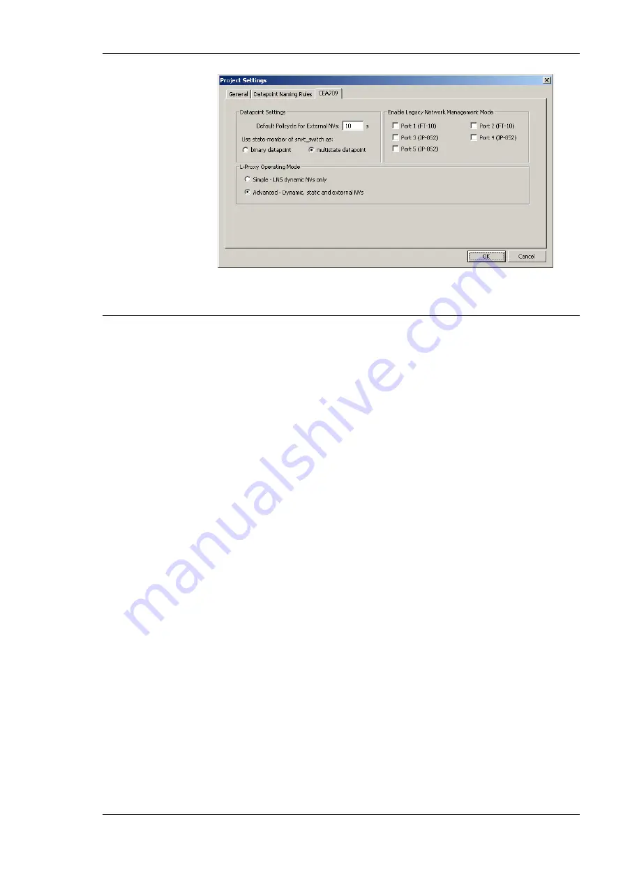
Figure 62: CEA-709 Project Settings.
7.4 Workflows for the L-Proxy
This section discusses a number of work flows for configuring the L-Proxy in different use
cases in addition to the simple use case in the quick-start scenario (see Chapter 2). The
description is intended to be high-level and is depicted in flow diagrams. The individual
steps refer to later sections, which describe each step in more detail. In principle, the L-
Proxy Configurator supports the following use cases:
•
Network Management Tool based on LNS 3.x (see Section 7.4.2),
•
network Management Tool based on LNS 3.x using a static NV interface (see Section
7.4.3),
•
non-LNS 3.x network management tool (see Section 7.4.4).
7.4.1 Involved Configuration Files
In the configuration process, there are a number of files involved:
•
Port interface definition file: This type of file contains all data points and their settings
for one port of the L-Proxy. This file is exported from and imported into the
Configurator software to exchange port interface definitions between the integrators.
These files end with “.itf”.
•
XIF file: This is the standard file format to exchange the static interface of a device.
This file can be used to create a device in the database without having the L-Proxy on-
line. There exists a standard XIF file for the FT port (L-Proxy_V3_0_FT-10.xif) and
one for the IP-852 port (L-Proxy_V3_0_IP-10L.xif).
•
L-Proxy Configurator project file: This file contains all ports, data points, and
connections of a project. These files end with “.lprxy”. It stores all relevant
configuration data and is intended to be saved on a PC to backup the L-Proxy’s data
point configuration. Alternatively to exchanging the port interface definition files, the
integrators can also pass on the project file. In this case, however, integrators can only
work incremental. As an advantage, the internal connections can already be created
partly during the process instead of creating all connections in the end.
7.4.2 Configure with LNS and Dynamic NVs
The flow diagram in Figure 63 shows the steps that need to be followed in order to install
L-Proxy in a network with LNS 3.x and using dynamic NVs. For this workflow the simple
operation mode is sufficient and no LNS database changes occur.
Summary of Contents for L-Proxy
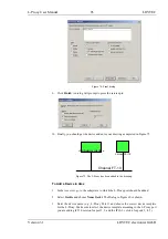
Page 1: ...L Proxy CEA 709 Gateway User Manual LOYTEC electronics GmbH ...
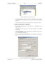
Page 10: ......


