background image

27

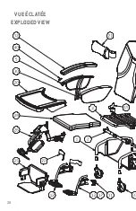
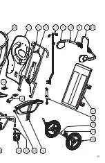
PARTS LIST

N

o

Code

Description

1

SP-010-xx*

Base assembly

2

SP-020-xx*

Pivot assembly

3

SP-030-xx*

Seat assembly

4

SP-040

LEFT armrest assembly

5

SP-041

RIGHT armrest assembly

6

SP-050-xx*

Backrest assembly

7

SP-070

Trunk support – support assembly

8

SP-072

Trunk supports

9

SP-073

Trunk support replacement cushion

10

SP-074

Trunk support adjustment plate

11

SP-080

Footrest support assembly

12

SP-085R

Right footrest assembly

13

SP-085L

Left footrest assembly

14

SP-094 

ou SP-094-SE**

Pair of 13" (33 cm) wheel brakes with 1 ¼" or 1 1/2" (SE) 

tube fittings

15

SP-328 ou SP-355R 

(S-150-22 & 24)

Right backrest adjustment plate

16

SP-329 ou SP-355L 

(S-150-22 & 24)

Left backrest adjustment plate

17

SA-10

Removable and retractable footrests

18

SA-20

Retractable and adjustable trunk support assemblies

19

SA-30-xx*

Set of 13" (33 cm) rear wheels with brakes

20

SA-40-xx*

Removable activity tray

21

SA-50

Cervical support

22

SA-70

Heel support loops

23

SA-75

IV pole with rear attachment (right side only)

24

SA-85

Tool-less depth adjustment

25

SA-120-xx*  **

Full-width footrest (requires option SA-10)

26

SA-130L/R/P

Adjustable elevating leg rest (L = left, R = right, P = pair)

27

SA-215-xx*  **

Adjustable tension backrest

28

SU-01-xx*  **

Backrest cushion

29

SU-02P-xx*  **

Pressure distribution seat cushion

30

SU-03**

Lateral armrest cushion (pair)

31

SU-04 ou AL40306 

(S-150-16)

Black plastic backrest shell, except for S-150-16: painted 

aluminum plate

32

SU-05

Black polyurethane armrest, right or left

33

SW-01

5" (13 cm) swivel wheel

34

SW-02

Fixed 5" (13 cm) wheel with brake

35

CYL-S01 ou CYL-S02 

(S-150-22 et 24)

Gas spring

36

HO40910

Painted anti-rotation plate for 5" wheel (1 ¼" tube)

37

QCL5000

5

Gas spring activation handle with cable

38

QWE13009

Single 13” wheel

39

XPE65052L

Guide end for table slide, left side

40

XPE65052R

Guide end for table slide, right side

*  Replace “xx” in the part n

o

 with the chair’s width (16", 18", 20", 22" or 24"). For cushions, use

18" for a 20" chair and 24" for a 22" chair.

**  Always specify the color, width, fabric pattern and serial number of your Dyn-Ergo chair when 

ordering replacement parts. See page 21 for the location of the serial number. Replacement 

parts may have slight color differences from those of the original chair. LPA Medical cannot be 

held responsible for these differences.

– Edited on 2021-

11

 –

Summary of Contents for Dyn-Ergo S-150

Page 1: ...1 INSTRUCTION MANUAL mobility chair Dyn Ergo S 150 FOCUSED ON WHAT MATTERS lpamedical com 2527 Dalton avenue Quebec Qc G1P 3S6 CANADA T 418 681 1313 1 800 663 4863 F 418 681 4488...

Page 2: ...into an aesthetic design that helps maintain the user s dignity and well being Please read this instruction manual carefully and consult it often to maximize the benefits of your LPA chair If you have...

Page 3: ...eat to Floor Height 10 Seat Depth 11 Seat Backrest Angle 12 Tilt in Space 14 Armrest Height 17 Lateral Supports Optional 18 Using the Footrests Optional 20 Serial Number Location 21 Options and Access...

Page 4: ...y or loved ones using this chair to follow the instructions in this manual at all times and to ensure proper care and maintenance of the LPA chair LPA Medical Inc accepts no responsibility for any bre...

Page 5: ...ot be allowed to use the chair APPLICATIONS The Dyn Ergo chair is designed primarily for long term care or to be used at home for self sufficiency and rehabilitation It allows patients at risk of fall...

Page 6: ...ure that The brakes are applied The patient s arms are inside the armrests The patient s legs are positioned in the center of the seat There is no pinch point possible During transfers the tilt should...

Page 7: ...dcoveringmanufacturer srecommendationsforcleaning Check with your supplier that the products you use are compatible Thechairshouldnotbepressure washedorplacedinsideawashing machine Thesepracticesmayca...

Page 8: ...rom 13 1 2 to 18 1 2 34 cm to 47 cm in 1 inch increments 2 The seat depth is adjustable from 13 3 4 to 18 35 cm to 46 cm 3 The seat backrest angle is adjustable from 91 to 115 degrees in 8 degree incr...

Page 9: ...rakesandredactivatinglevers at the rear To apply the brakes 1 Using your toe apply pressure on the ends of the red activation levers of the two rear wheels WARNING BEFOREHANDLINGANOCCUPANTORMAKINGANAD...

Page 10: ...KE SURE BOTH SIDES ARE AT THE SAME LEVEL Put back the 4 bolts without forgetting the flat washers and the lock washers Tighten properly 4 Put the chair back on its wheels and have the user try it to e...

Page 11: ...th sides at the same time so that the backrest moves uniformly 4 When the appropriate depth is reached and equal on both sides firmly tighten the 4 bolts 5 Get the user to try it and readjust it if ne...

Page 12: ...ingtominimizetheriskofjammingfingers Itwillmake the operation easier 1 Determine in advance the backrest tilt adjustment required 2 Apply the brakes hold the chair on both sides and lay it on its side...

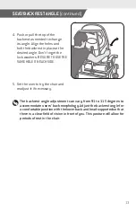
Page 13: ...URE TO USE THE SAME HOLE ON EACH SIDE 5 Get the user to try the chair and readjust it if necessary The backrest angle adjustment can vary from 91 to 115 degrees to accommodate users back morphology Ad...

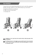
Page 14: ...n obtain A Significant assistance standing up B Slight assistance standing up C A backward tilt TILT IN SPACE AWARNING THE CHAIR MUST BE UNOCCUPIED WHEN MAKING THIS ADJUSTMENT Forthisoperation itisstr...

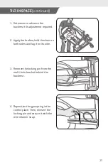
Page 15: ...nt required 2 Apply the brakes hold the chair on both sides and lay it on its side 3 Remove the locking pin from the multi hole bracket behind the backrest 4 Reposition the gas spring in the correct p...

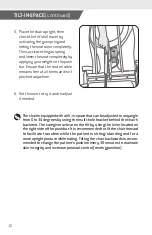
Page 16: ...readjust if needed Thechairisequippedwithatilt in spacethatcanbeadjustedtoanyangle from 0 to 34 degrees by using the multi hole bracket behind the chair s backrest The caregiver activates the tilt by...

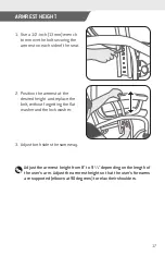
Page 17: ...rest at the desired height and replace the bolt without forgetting the flat washer and the lock washer 3 Adjust both sides the same way Adjust the armrest height from 8 to 9 1 2 depending on the lengt...

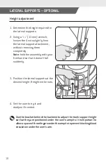
Page 18: ...free hand so that it doesn t fall suddenly 3 Position the lateral supports at the desired height Retighten the nuts 4 Get the user to try it and readjust if needed Use the bracket behind the backrest...

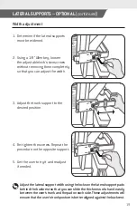
Page 19: ...he width 3 Adjust the trunk support to the desired position 5 Get the user to try it and readjust if needed Adjustthelateralsupportwidthusingthelocksonthelateralsupportpads behindthebackrestsothatyouc...

Page 20: ...you will hear a click 2 Lower the footrest 3 Repeat the operation on the other side 4 To store the footrest raise the footrest upward activate the black lever and pivot the footrest outward until it...

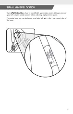
Page 21: ...chair is identified by a serial number Always provide your LPA chair s serial number when ordering replacement parts The serial number can be found on a label affixed to the rear cross tube of the bas...

Page 22: ...SA 215 Adjustable tension backrest SU 07 Black vinyl padded armrest AB 08H Contoured headrest with universal attachment harness AC 04 Leatherette padded tray cover AE 02 Universal drainage bag holder...

Page 23: ...st bewell fitting sothatahandwiththepalmopencanpassbetweenthestrap and the user s body Never use positioning straps as a means of restraining the user Improper use can result in serious injury or even...

Page 24: ...s while sitting on the seat Slide the buttocks backwards and lower slowly while continuing to lean forward Slide the buttocks into the back of the chair MOVING USING FEET It is possible to move with t...

Page 25: ...d damage during this period will void the LPA Medical Inc warranty Additional costs of handling and or using a platform when unloading may apply and are at the customer s expense RETURNS Merchandise t...

Page 26: ...Model serial and part 2 Purchase date and invoice number 3 Description of the problem The useful lifespan of an LPA chair is estimated to be 10 years OUR COMMITMENT LPAMedicalinc agreestoprovidereplac...

Page 27: ...ull width footrest requires option SA 10 26 SA 130L R P Adjustable elevating leg rest L left R right P pair 27 SA 215 xx Adjustable tension backrest 28 SU 01 xx Backrest cushion 29 SU 02P xx Pressure...

Page 28: ...28 VUE CLAT E EXPLODED VIEW...

Page 29: ...29...

Reviews: