background image

1 4


IMPORTANT SAFETY INFORMATION

• Never touch the patient and the device’s 

unprotected cables or connectors 
simultaneously.

•  Never use the adapter as a treatment head 

or allow it to come into direct contact with the 
skin. 

•  Only use treatment heads supplied with your 

unit or recommended by LPG

®

.

•  Do not use the treatment heads directly on the 

skin. Use the treatment suits provided by LPG 
Systems only, ENDERMOWEAR

TM

.

•  LPG Systems will not be liable for any 

inappropriate use of the equipment. 

•  Improper use of the device can cause tissue 

damage or pain.

•  The operator must be particularly attentive to 

the sensations felt by the patient undergoing 
treatment.

•  The operator must ensure that the settings 

(intensity, sequentiality, differential, etc.) are 
always adapted to the tissue being treated..

•  Do not put more than 135 kg on the seat.
•  Do not put more than 10 kg on the head 

storage tray.

•  When the table is being used without 

supervision, it should be put in the lowest 
position to avoid the risk of falling.

•  After use, put the table in the lowest position 

to avoid the risk of falling.

• Do not lean, rest or sit on the head storage 

tray.

•  Do not use the USB connection during 

treatment.

•  Do not operate the unit in unsuitable 

environmental conditions (see technical 
specifications).

•  It is recommended to use a treatment sheet on 

the seat.

•  The power plug is used as a disconnect device. 

The disconnection of the unit is possible by 
disconnecting the power plug. 

•  Please position your device so that the power 

supply unit is always accessible.

•  Do not touch the patient and the hose 

connectors simultaneously.

• Do not use vegetable oil on the treatment 

heads.

ATTENTION : KEEP THESE INSTRUCTIONS.
Your device should be used on healthy skin. It is important to read and respect the following 

precautions and contraindications before using your device.

3

IMP

OR

T

ANT SAFET

Y INF

ORMA

TION

Summary of Contents for CELLU M6 Alliance Lab Medical

Page 1: ...e read the complete manual carefully before using your equipment LPG Systems 2020 LPG ENDERMOWEARTM and ENDERMOLOGIE are registered trademarks of LPG SYSTEMS Reproduction even in part is strictly prohibited CELLU M6 Alliance Lab Medical Registered design ...

Page 2: ...ously provide satisfaction your device is equipped with a specific software ensuring connection with the LPG dedicated server The data collected through this software will allow LPG to give you better services in terms of support and maintenance This operator s manual contains the operating description basic maintenance instructions to be performed periodically and the safety instructions Your dev...

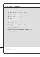
Page 3: ...cal device One Alliance 80 treatment head One Alliance 50 treatment head One TR30 treatment head One set of micro nozzles and micro heads One Ergolift treatment head Two Ergolift chambers Lift20 and Lift10 One electrical power cord One unpacking instructions and quick installation guide One marketing set ...

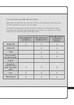
Page 4: ... In case you have any doubt about the operation of your device or to evolve into a complete model please contact LPG Systems After Sales Service List of accessories provided with your device Cellu M6 Alliance Lab Medical Cellu M6 Alliance Lab Medical Plus Cellu M6 Alliance Lab Medical Premium Alliance 80 Alliance 50 TR30 Micro nozzles and micro heads Ergolift Unpacking instructions and quick insta...

Page 5: ...rohibited All the illustrations in this operator s manual are non binding AT T E N T I O N 1 DEVICE DESCRIPTION 5 2 CONTROLS DESCRIPTION 8 3 IMPORTANT SAFETY INFORMATION 12 4 MAINTENANCE 18 5 TROUBLESHOOTING 28 6 TECHNICAL SPECIFICATIONS 29 7 TREATMENT HEADS 30 8 ENDERMOWEARTM 45 9 GENERAL WARRANTY CONDITIONS 46 10 APPENDIX ELECTROMAGNETIC COMPATIBILITY 50 ...

Page 6: ...skin quality scars and fibrosis 12 Improve skin ageing wrinkles fine lines sagging skin fat infiltration firmness elasticity complexion and dark circles and puffiness 13 Stimulate fibroblasts collagen elastin and hyaluronic acid synthesis The device can be used in hospitals therapy centers and institutions by specialists and physiotherapists It can be used on adult patients only of any sex with a ...

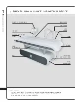
Page 7: ... After switching on the unit please wait a few seconds for the screen to display information AT T E N T I O N HOSE HOLDER HEAD HOLDER FILTER ACCESS DOOR HEAD STORAGE TRAY FRONT SIDE TOUCHSCREEN IHM ARMS HEAD HOLDER DRAWER MAINS PLUS SWITCH AND POWER ADJUSTABLE TREATMENT TABLE BOX HOSE THE CELLU M6 ALLIANCE LAB MEDICAL DEVICE D E V I C E D E S C R I P T I O N 1 ...

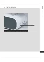
Page 8: ...7 FILTER ACCESS 1 D E V I C E D E S C R I P T I O N FILTER THE FILTER IS ACCESSIBLE ON THE SIDE OF THE BOX ...

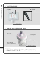
Page 9: ...touch interface operating manual received during training and available from customer service AT T E N T I O N CONTROL SCREEN ALLIANCE 80 TREATMENT HEAD C O N T R O L S D E S C R I P T I O N 2 PARAMETER SETTING BUTTONS EMBELLISHER FLAP BRIGHT LEDS ADJUSTMENT SLIDER POSITION FOR ROLL AND FLAP MOTORISED ROLL AND FLAP ...

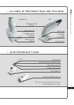
Page 10: ...MOTORISED ROLLS AND FLAP ADJUSTMENT SLIDER POSITION ROLL AND FLAP ALLIANCE 50 TR30 SEALING FLAP MOTORISED ROLLS ADJUSTEMENT SLIDER POSITION ROLL SELECTION BUTTON FOR TREATMENT TYPE POWER INCREASE BUTTON POWER DECREASE BUTTON ON OFF BUTTON HOSE CONNECTION ERGOLIFT CHAMBER CONNECTION They can be connected and disconnected by a simple push pull action ...

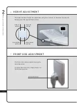
Page 11: ...be adjusted using the articulated dial To adjust the front side simply move it to the desired position ARTICULATED DIAL BACK DOWN BUTTON TABLE DOWN BUTTON BACK UP BUTTON TABLE UP BUTTON The table and back height are adjustable using the controls on the table see photo Simply press the appropriate buttons ...

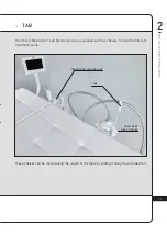
Page 12: ...TREATMENT HEAD HOLDER LINE TREATMENT HEAD HOLDER The CELLU M6 Aliance Lab Medical device is equipped with two shelves to hold the different treatment heads These shelves can be moved along the length of the table by sliding it along the provided rail ...

Page 13: ...ta plate complies with the power supply voltage The unit must be connected by the power cord supplied to a grounded outlet in accordance with current electrical standards Electrical adapters must not be used with this equipment Ensure that the unit is connected to a system with a differential protection against DC and AC DANGER TO MINIMISE THE RISK OF ELECTRICAL SHOCK I M P O R T A N T S A F E T Y...

Page 14: ...ation ports are obstructed Ensure that the ventilation ports are kept clear of dust or other contaminants Do not allow solid debris liquid or other foreign bodies to fall or be sucked into the unit as these could cause damage Never use the equipment on a dusty uneven floor or in a moist atmosphere Never use the equipment in the presence of aerosols or oxygen Before disconnecting the unit from the ...

Page 15: ...more than 10 kg on the head storage tray When the table is being used without supervision it should be put in the lowest position to avoid the risk of falling After use put the table in the lowest position to avoid the risk of falling Do not lean rest or sit on the head storage tray Do not use the USB connection during treatment Do not operate the unit in unsuitable environmental conditions see te...

Page 16: ... or an infected area Do not treat a patient with skin cancer a visible tumour or other cancerous lesions Consult with a doctor in cases where the patient has a case history of tumours or is in remission Do not treat inflammatory areas or scars without medical advice and LPG technical training for the affected areas Do not treat patients with circulatory problems without first consulting their doct...

Page 17: ...se caution when determining a patient s level of sensitivity and avoid use on patients taking anticoagulant drugs Stop treatment immediately if the patient experiences pain and consult a doctor This device should not be used on all dermatoses skin rashes herpes inflammatory or infectious acne or vitiligo Because of the risk of interference it is important that the professional ensures the patient ...

Page 18: ...reatment heads other than those provided by LPG Systems may result in increased emissions or decreased immunity of the device Your CELLU M6 Alliance Lab Medical device should not be used adjacent to or stacked with other medical devices The Cellu M6 Alliance Lab Medical device does not manage essential performances Interference may occur near equipment marked with the following symbol For more inf...

Page 19: ... LPG Systems because of a technical problem please indicate the serial number of your CELLU M6 Alliance Lab Medical device This serial number provides information on the year and month of manufacture of your unit The letter indicates the year the device was manufactured Z 2009 A 2010 B 2011 etc The two digits indicate the production month 01 January 02 February 03 March etc serial number voltage f...

Page 20: ...t the accompanying documents before using your device This symbol indicates the name and address of the manufacturer This symbol means that your device has type BF applied parts which come into contact with the patient These parts are electrically isolated from all of the device s other parts These applied parts are the treatment heads This symbol means store the device somewhere protected from in...

Page 21: ... storage drawer Interior of the head storage tray Interior of the filter access door Using a moist sponge clean the following sections All the external hoods Hoses The electrical power cord Using a cloth soaked with a small amount of alcohol free domestic cleaning product clean the following sections Control screen and control panel Interior of the head storage drawer Interior of the head storage ...

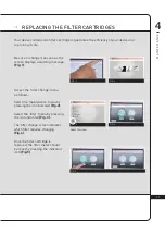
Page 22: ...it as soon as the screen displays a warning message Fig 1 Access the filter change menu as follows Select the maintenance menu by pressing the icon indicated Fig 2 Select the filter menu by pressing the icon indicated Fig 3 The filter change screen indicates which filter requires changing Fig 4 Once the filter cartridge is replaced the filter meter should be reset by pressing the indicated icon Fi...

Page 23: ...ns one filter cartridge to guarantee the efficiency of your device and to porlong its life Be sure to change it as soon as the screen displays a warning message Open the filter access door Unscrew the filter cartridge and replace it with a new one Contact LPG Systems Customer Support to stock up on filter filter cartridges so that you always have spares M A I N T E N A N C E ...

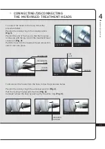
Page 24: ...lot of the treatment head connection Fig 2 Push the hose into the treatment head connection until it cliks into place UNLOCKED LOCKED FIG 2 FIG 4 FIG 5 FIG 3 FIG 1 LOCKING RING ORNAMENTAL RING LOCKED POSITION HOSE KEY KEY SLOT To disconnect the heads from the hose follow the procedure below Position the locking ring in the unlocked position Fig 3 Pull the locking ring towards the hose Fig 4 Carefu...

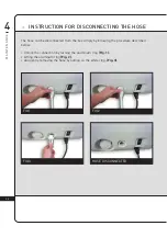
Page 25: ... from the box simply by following the procedure described below Unlock the connection by turning the aluminum ring Fig 1 Lifting the aluminum ring Fig 2 And gently removing the hose by pulling on the white ring Fig 3 FIG 1 FIG 3 FIG 2 HOSE DISCONNECTED M A I N T E N A N C E ...

Page 26: ...t the hose adapter follow the procedures described in Chapter 4 4 Connecting Disconnecting the motorised treatment heads The connection is made with a simple push pull movement HOSE CONNECTION TREATMENT HEAD CONNECTION Only the micro heads and the micro nozzles can be connected to the adapter The connection is made with a simple push pull movement ...

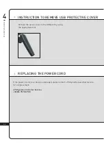
Page 27: ... access cover to the USB port by using the appropriate tool M A I N T E N A N C E REPLACING THE POWER CORD If the power cord of your device is damaged please contact LPG Systems Customer Service for a replacement LPG Systems Customer Service 33 0 4 75 78 69 00 ...

Page 28: ...eplacement of filter cartridges To be done when the warning message appears Replacement of sealing flap To be done when the flaps no longer treat the skin properly They should be replaced after every 100 hours of use DATE N OF HOURS OPERATION PERFORMED ...

Page 29: ...it up Are the filter cartridges clean and correctly placed Are the hoses properly connected Is the treatment head properly connected Does the connected treatment head correspond to that shown on the screen Once these checks have been carried out and if the malfunction persists please contact Customer Services of LPG Systems or the nearest authorised distributor indicating the model of your unit an...

Page 30: ...mental features Ambient temperature 10 C to 30 C for normal use Ambient relative humidity 30 to 75 without condensation Atmospheric pressure 800 to 1050 hPa to be used in a normally ventilated room Max altitude 2 500 m Environmental characteristics of transport and storage Temperature 20 C to 70 C Ambient relative humidity 10 to 90 without condensation Atmospheric pressure 800 to1050 hPa to be use...

Page 31: ...3 0 7 T R E A T M E N T H E A D S TREATMENT HEADS Registered design ...

Page 32: ...D E T R A I T E M E N T alliance 80 HEAD description 32 alliance 50 HEAD description 34 tr30 HEAD description 36 ADAPTER description 37 ERGOLIFT HEAD description 37 MICRO NOZZLES AND MICRO HEADS description 38 MAINTENANCE 39 ...

Page 33: ...CRIPTION BRIGHT LEDS START STOP BUTTON The Alliance 80 head can be used to the Endermologie body treatment PARAMETER SETTING BUTTONS EMBELLISHER FLAP NAVIGATION BUTTONS ADJUSTMENT SLIDER POSITION ROLL AND FLAP EMBELLISHER FLAP MOTORISED FLAP MOTORISED ROLL ...

Page 34: ... between the motorised roll and the damper When the cursor is in the horizontal position the maximum mobility of the rolls is ensured When the cursor is in the vertical position the minimum mobility of the rolls is ensured MINIMUM SPACING POSITION MAXIMUM SPACING POSITION To change the adjustment slider turn it while holding it down to the desired position as shown in the photo below ...

Page 35: ... the therapeutic treatment fibrosis edema inflammation etc PARAMETER SETTING BUTTONS NAVIGATION BUTTONS START STOP BUTTON EMBELLISHER FLAP MOTORISED FLAP ADJUSTEMENT SLIDER POSITION ROLL AND FLAP MOTORISED ROLL MOTORISED FLAP TREATMENT CHAMBER T R E A T M E N T H E A D S ...

Page 36: ...l and flap When the cursor is in the horizontal position the maximum mobility of the rolls is ensured When the cursor is in the vertical position the minimum mobility of the rollers is ensured MINIMUM SPACING POSITION MAXIMUM SPACING POSITION To change the adjustment slider turn it while holding it down to the desired position as shown in the photo below T R E A T M E N T H E A D S ...

Page 37: ...3 6 7 T R E A T M E N T H E A D S TR30 HEAD DESCRIPTION PARAMETER SETTING BUTTONS ROLLS LOCKING MECHANISM START STOP BUTTON SEALING FLAP MOTORISED ROLLS ...

Page 38: ...ift 10 Treatment chamber with removable flap SELECTION BUTTON FOR TREATMENT TYPE POWER INCREASE BUTTON POWER DECREASE BUTTON ON OFF BUTTON HOSE CONNECTION ERGOLIFT CHAMBER CONNECTION They can be connected and disconnected by a simple push pull action The Ergolift chamber Lift 20 can be used for the treatment of large areas with fine tissues and sensitive areas The Ergolift chamber Lift 10 can be u...

Page 39: ...3 8 7 T R E A T M E N T H E A D S MICRO HEADS AND MICRO NOZZLES DESCRIPTION NOZZLE CONNECTIVE TR 15 HEAD MICRO NOZZLES MICRO HEADS ...

Page 40: ...laps two up flaps and one down flap as shown in the pictures below Fig 1 to 4 2 Thoroughly rub for at least one minute with the wipes as described below a Flaps and their housing Fig 5 to 7 b The casing on both sides of the rolls turn the head over rotate the rolls manually to clean the entire surface Fig 8 c The motorized flap Do not mobilise the motorised flap Fig 9 10 d Sabot 3 Reattach the sea...

Page 41: ... as showed in the pictures below Fig 1 to 4 2 Thoroughly rub for at least one minute with the wipes as described below a Flaps and their housing Fig 5 to 7 b The casing on both sides of the rolls turn the head over rotate the rolls manually to clean the entire surface Fig 8 c The motorised flap Do not mobilise the motorised flap Fig 9 10 d Sabot 3 Reattach the sealing flaps 4 Maintain the storage ...

Page 42: ... wipes as described here below a The flaps and their housing Fig 2 3 b The casing on both sides of the rolls turn the head over rotate the rolls manually to clean the entire surface Fig 4 c Sabot 3 Reattach the sealing flaps 4 Maintain the storage drawer using LPG wipes then place the head in it T R E A T M E N T H E A D S Fig 1 Fig 2 Fig 3 Fig 4 ...

Page 43: ...t least one minute the rolls seal treatment chamber microheads disassembly tool and micro nozzles with LPG wipes soaked in a bactericide and fungicide solution Fig 3 4 Refit the rolls and check they spin freely 5 To maintain the micro heads use cotton soaked with the same solution 6 Maintain the storage drawer using LPG wipes then place the heads in it MICRO HEADS AND MICRO NOZZLES MAINTENANCE 7 ...

Page 44: ...ully rinse the flap and the treatment chamber with sterile or drinking water for at least one minute using a large volume of water approximately eight litres Repeat twice for a total of three rinses 4 Dry the parts 5 Pre clean the storage drawer using LPG wipes then place the head in it Use a disinfectant whose active ingredient is ortho phthalaldehyde OPA Before using the disinfectant read and fo...

Page 45: ...al and fungicidal solution Special attention must be given to the cleanliness of the parts that are in contact with the patient 1 Disconnect the chamber from the Ergolift treatment head Fig 1 2 Remove the flap using the dedicated tool Fig 2 3 Thoroughly rub the Ergolift chamber the flap and the tool for at least one minute with the wipes as described below Fig 3 4 Put the flap back in the Ergolift...

Page 46: ...cleaned and or disinfected heads should be placed in the storage drawer to avoid any confusion Use a disinfectant whose active ingredient is ortho phthalaldehyde OPA Before using the disinfectant read and follow the recommendations contraindications and warnings associated with this product Refer to the instructions for using this solution All the procedures described in this section must be carri...

Page 47: ...s that are only partially completed will be rejected The appliance is guaranteed against manufacturing flaws and defects in the raw materials The warranty extends for the shorter of the following two periods two 2 years OR two thousand 2000 hours of use from the invoice date During this period LPG Systems undertakes to exchange or repair free of charge as quickly as possible any part that LPG Syst...

Page 48: ...ed on the appliance Modification mounting of accessories or dismantling of the equipment Any operation and or intervention not specified in the LPG Systems Operating Instructions and performed on the equipment by the purchaser user and or any party not approved by LPG Systems Use of consumables spare parts inappropriate components or parts not supplied by LPG Systems Blockage of the appliance thro...

Page 49: ...The purchaser user is responsible for the use of the device and will assume full responsibility for any damages including damages caused to third parties resulting from the failure to observe the instructions for use of the device and or resulting from an improper use Under no circumstances will LPG SYSTEMS be held liable for any intangible or indirect damages including any commercial or financial...

Page 50: ...4 9 9 G E N E R A L W A R R A N T Y C O N D I T I O N S WARRANTY ACTIVATION You can activate your warranty online by connecting to our warranty webpage http warranty lpgsystems com ...

Page 51: ...ions IEC 61000 3 2 Class A Voltage fluctuations and flicker IEC 61000 3 3 Conforms TABLE 2 IMMUNITY Test Requirements Level of conformity Electrostatic discharge DES IEC 61000 4 2 8 kV on contact 2 4 8 15 kV in the air 8 kV on contact 2 4 8 15 kV in the air Radiated RF electromagnetic fields IEC 61000 4 3 10V m 80MHz 2 7 GHz 80 AM at 1 kHz 10V m 80MHz 2 7 GHz 80 AM at 1 kHz Proximity fields issued...

Page 52: ... at 1 kHz 3 V 0 15 MHz 80 MHz 6 V in ISM bands and amateur radio bands between 0 15 MHz and 80 MHz 80 AM at 1 kHz Power frequency magnetic field IEC 61000 4 8 30 A m 30 A m Voltage Dips and Interruptions IEC 61000 4 11 0 UT 0 5 cycle A 0 45 90 135 180 225 270 et 315 0 UT 1 cycle at 0 70 UT 25 30 cycles at 0 0 UT 250 300 cycles 0 UT 0 5 cycle A 0 45 90 135 180 225 270 et 315 0 UT 1 cycle at 0 70 UT...

Page 53: ...0 4 75 42 80 85 INTERNATIONAL MARKETING ECOLUCIOLES BAT A 955 RTE DES LUCIOLES BP 243 06905 SOPHIA ANTIPOLIS FRANCE TEL 33 0 4 92 38 39 00 FAX 33 0 4 92 96 09 65 1571 Ed 07 20 GB LPG Systems 2020 LPG Systems S A S au capital de 2 124 950 euros Siren RCS 335 183 836 Romans Any reproduction even in part is strictly prohibited Non binding photos ...

Reviews: