background image

3 9

3 9

8


>

MAINTENANCE


>

ENDERMOWEAR

TM

LPG Endermowear’s

TM

 suit is available in several sizes for men and women and has been 

specially designed for body treatments. It is intended for personal use, guarantees hygiene 

and its opaque areas cover the patient’s intimate parts during the treatment. Endermowear

TM

’s 

unique material guarantees excellent adhesion to the skin which facilitates movement of the 

treatment head.

The products are delivered in a bag that the customer can personalise  by putting their name 

on the label. It becomes the customer’s property and can be used for several sessions. 

For aesthetic and hygienic reasons, it should be washed after each use. Please refer to the 

washing instructions indicated on the bag label.

ENDERMO

WEAR

TM

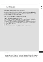
DESINFECTING OF ERGOLIFT CHAMBERS

The use of aggressive products, such as acetone, trichloroethylene, or alcohol at 90° and abrasive sponges, ultrasound 

or UV lamps is strictly prohibited. All cleaned and/or disinfected heads should be placed in the storage drawer to avoid 

any confusion. Use a disinfectant whose active ingredient is ortho-phthalaldehyde (OPA). Before using the disinfectant, 

read and follow the recommendations, contraindications and warnings associated with this product. Refer to the 

instructions for using this solution. All the procedures described in this section must be carried out with the machine 

turned off and the power cord unplugged.

A T T E N T I O N

The Ergolift head is in direct contact with patient’s skin. Under certain specific applications, 

it needs to be disinfected after each use:

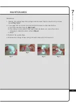
1. Follow the maintenance procedure described below.
2. Soak the flap and Ergolift chamber in an OPA disinfectant for 12 minutes at 20 °C,  

as recommended on the disinfectant packaging.

3. Carefully rinse the flap and the Ergolift chamber with sterile or drinking water for at least 

one minute using a large volume of water (approximately eight litres). Repeat twice for a 

total of three rinses.

4. Dry the Ergolift chamber and flap.
5. Clean the storage drawer with antiseptic wipes then place the Ergolift chamber and flap 

in it.

Summary of Contents for CELLU M6 Alliance Medical

Page 1: ...omplete manual carefully before using your equipment Copyright 2020 LPG Cellu M6 EndermowearTM and Endermologie are registered trademarks of LPG SYSTEMS and or trademarks on which it holds exclusive r...

Page 2: ...ction your device is equipped with a specific software devised to ensure connection with the LPG Systems dedicated server The data collected through this software will allow LPG Systems to give you be...

Page 3: ...l device One Alliance 80 treatment head One Alliance 50 treatment head One TR30 treatment head One set of micro nozzles and micro heads One Ergolift treatment head Two Ergolift chamber Lift20 and Lift...

Page 4: ...In any doubt about the operation of your unit or to evolve into a complete model please contact the Customer Service of LPG Systems or your distributor List of accessories provided with your device Ce...

Page 5: ...illustrations in this operator s manual are non binding AT T E N T I O N TABLE OF CONTENTS 1 DEVICE DESCRIPTION 5 2 CONTROLS DESCRIPTION 7 3 IMPORTANT SAFETY INFORMATION 10 4 MAINTENANCE 14 5 TROUBLES...

Page 6: ...reas 11 Improve skin quality scars fibrosis 12 Improve skin aging wrinkles fine lines skin sagging fat infiltration firmness elasticity complexion and eye bags 13 Stimulatie fibroblasts collagen elast...

Page 7: ...ds for the screen to display information AT T E N T I O N D E V I C E D E S C R I P T I O N 1 THE CELLU M6 ALLIANCE MEDICAL DEVICE CASTER LOCKING MECHANISM LEFT HOSE FORWARD FACING TOUCHSCREEN HEAD HO...

Page 8: ...anual received during training and available from customer service AT T E N T I O N FILTER ACCESS C O N T R O L S D E S C R I P T I O N 2 CONTROL SCREEN LEFT HOSE FILTER RIGHT HOSE FILTER FILTER ACCES...

Page 9: ...BUTTONS EMBELLISHER FLAP BRIGHT LEDS ADJUSTEMENT SLIDER POSITION ROLLER AND FLAP MOTORISED ROLLER AND FLAP PARAMETER SETTING BUTTONS EMBELLISHER FLAP MOTORISED ROLLER AND FLAP ADJUSTEMENT SLIDER POSI...

Page 10: ...Medical device AT T E N T I O N ERGOLIFT HEAD ADAPTER CASTERS 2 C O N T R O L S D E S C R I P T I O N SELECTION BUTTON FOR TREATMENT TYPE POWER INCREASE BUTTON POWER DECREASE BUTTON ON OFF BUTTON HOSE...

Page 11: ...L SHOCK TO MINIMISE THE RISK OF BURNS FIRE ELECTRICAL SHOCK OR INJURY The device must not be left unattended while connected to the electrical supply Disconnect the unit from the electrical supply if...

Page 12: ...ssing a threshold or step we recommend moving the unit carefully by firmly holding the central arm monitor stand to avoid the risk of tipping Do not use the USB connection during treatment Do not oper...

Page 13: ...latory problems without first consulting their doctor and without LPG Technical training for the affected areas Do not treat a patient with an unexplained and persistent pain without medical advice an...

Page 14: ...device they can cause undesired operation The use of treatment heads other than those provided by LPG may result in increased emissions or decreased immunity of the device Your CELLU M6 Alliance Medi...

Page 15: ...fe it must be brought to an appropriate recycling centre or returned to your dealer By doing so you help the environment by contributing to the conservation of natural resources and the protection of...

Page 16: ...s Interior of the head storage drawer Interior of the head storage tray Interior of the filter access door Using a moist sponge clean the following sections All the external hoods Hoses The electrical...

Page 17: ...ng its useful life FIG 5 FIG 4 FIG 1 FIG 3 FIG 2 Ensure that they are changed as soon as the icon indicating a filter change appears on the screen Fig 1 Access the filter change menu as follows Select...

Page 18: ...h new ones Fig 2 and Fig 3 4 Remove the filter foam and replace it with a new one Fig 4 and Fig 5 Remember to purchase new filter cartridges from the LPG Systems Customer Service Department so you alw...

Page 19: ...up with the key slot of the treatment head connection Fig 2 Push the hose into the treatment head connection until it cliks into place FIG 3 FIG 1 LOCKING RING ORNAMENTAL RING LOCKED POSITION HOSE KE...

Page 20: ...the hose adapter follow the procedures described in chapter 4 4 Connecting Disconnecting the motorised treatment heads The connection is made with a simple push pull movement HOSE CONNECTION TREATMEN...

Page 21: ...N A N C E 4 REPLACING THE POWER CORD If the power cord of your device is damaged please contact LPG Systems Customer Service for a replacement LPG Systems Customer Service 33 0 4 75 78 69 00 Remove t...

Page 22: ...ridges To be done when the warning message appears Replacement of sealing flap To be done when the flaps no longer treat the skin properly They should be replaced after every 100 hours of use DATE N O...

Page 23: ...the ON switch lit up Are the filter cartridges clean and correctly placed Are the hoses correctly connected Is the treatment head properly connected Is the treatment head correctly connected Once the...

Page 24: ...bient temperature 10 C to 30 C for normal use Ambient relative humidity 30 to 75 without condensation Atmospheric pressure 800 to 1050 hPa to be used in a normally ventilated room Max altitude 2 500m...

Page 25: ...2 4 T R E A T M E N T H E A D S 7 CELLU M6 Alliance Medical TREATMENT HEADS Registered design...

Page 26: ...A T M E N T H E A D S 7 INDEX ALLIANCE 80 HEAD DESCRIPTION 26 ALLIANCE 50 HEAD DESCRIPTION 28 TR30 HEAD DESCRIPTION 30 ERGOLIFT HEAD DESCRIPTION 31 MICRO HEADS AND MICRO NOZZLES DESCRIPTION 32 MAINTE...

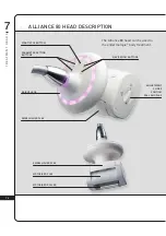
Page 27: ...IPTION BRIGHT LEDS START STOP BUTTON The Alliance 80 head can be used to the endermologie body treatment PARAMETER SETTING BUTTONS EMBELLISHER FLAP NAVIGATION BUTTONS ADJUSTMENT SLIDER POSITION ROLL A...

Page 28: ...e between the motorised roller and damper When the cursor is in the horizontal position the maximum mobility of the rollers is ensured When the cursor is in the vertical position the minimum mobility...

Page 29: ...liance 50 head can be used for therapeutic treatment fibrosis edema inflammation etc PARAMETER SETTING BUTTONS NAVIGATION BUTTONS START STOP BUTTON EMBELLISHER FLAP MOTORISED FLAP ADJUSTMENT SLIDER PO...

Page 30: ...ween the motorised roller and of the damper When the cursor is in the horizontal position the maximum mobility of the rollers is ensured When the cursor is in the vertical position the minimum mobilit...

Page 31: ...3 0 T R E A T M E N T H E A D S 7 TR30 HEAD DESCRIPTION PARAMETER SETTING BUTTONS ROLLER LOCKING MECHANISM START STOP BUTTON SEALING FLAP MOTORISED ROLLS...

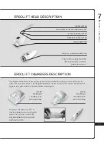
Page 32: ...ift 10 Treatment chamber with removable flap SELECTION BUTTON FOR TREATMENT TYPE POWER INCREASE BUTTON POWER DECREASE BUTTON ON OFF BUTTON HOSE CONNECTION ERGOLIFT CHAMBER CONNECTION They can be conne...

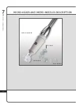
Page 33: ...3 2 T R E A T M E N T H E A D S 7 MICRO HEADS AND MICRO NOZZLES DESCRIPTION NOZZLE CONNECTIVE TR 15 HEAD MICRO NOZZLES MICRO HEADS...

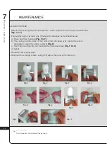
Page 34: ...ling flaps two up flaps and one down flap as shown in the pictures below Fig 1 to 4 2 Thoroughly rub for at least one minute with the wipes as described below a Flaps and their housing Fig 5 to 7 b Th...

Page 35: ...es as described below a Flaps and their housing Fig 5 to 7 b The casing on both sides of the rollers turn the head over rotate the rollers manually to clean the entire surface Fig 8 c The motorised fl...

Page 36: ...below Fig 1 to 4 2 Thoroughly rub for at least one minute with the wipes as described below a The flaps and their housing Fig 2 3 b The casing on both sides of the rollers turn the head over rotate t...

Page 37: ...least one minute the rollers seal treatment chamber micro heads disassembly tool and micro nozzles with LPG wipes soaked in a bactericide and fungicide solution Fig 3 4 Refit the rollers and check th...

Page 38: ...lly rinse the flap and the treatment chamber with sterile or drinking water for at least one minute using a large volume of water approximately eight litres Repeat twice for a total of three rinses 4...

Page 39: ...and fungicidal solution Special attention must be given to the cleanliness of the parts that are in contact with the patient 1 Disconnect the chamber from the Ergolift treatment head Fig 1 2 Remove th...

Page 40: ...ll cleaned and or disinfected heads should be placed in the storage drawer to avoid any confusion Use a disinfectant whose active ingredient is ortho phthalaldehyde OPA Before using the disinfectant r...

Page 41: ...hat are only partially completed will be rejected The appliance is guaranteed against manufacturing flaws and defects in the raw materials The warranty extends for the shorter of the following two per...

Page 42: ...n the appliance If an appliance is sold before the end of the warranty period the warranty is transferred to the purchaser for the remaining warranty period on the condition that I The original invoic...

Page 43: ...products The purchaser user is responsible for the use of the device and will assume full responsibility for any damages including damages caused to third parties resulting from the failure to observe...

Page 44: ...4 3 G E N E R A L W A R R A N T Y C O N D I T I O N S 9 WARRANTY ACTIVATION You can activate your warranty online by connecting to our warranty webpage http warranty lpgsystems com...

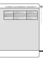
Page 45: ...C 61000 3 2 Class A Voltage fluctuations and flicker IEC 61000 3 3 Conforms TABLE 2 IMMUNITY Test Requirements Level of conformity Electrostatic discharge DES IEC 61000 4 2 8 kV on contact 2 4 8 15 kV...

Page 46: ...t 1 kHz 3 V 0 15 MHz 80 MHz 6 V in ISM bands and amateur radio bands between 0 15 MHz and 80 MHz 80 AM at 1 kHz Power frequency magnetic field IEC 61000 4 8 30 A m 30 A m Voltage Dips and Interruption...

Page 47: ...strictly prohibited Non binding photos HEADQUARTERS LPG SYSTEMS S A S TECHNOPARC DE LA PLAINE 30 RUE DU DR ABEL CS 90035 26902 VALENCE CEDEX 09 FRANCE TEL 33 0 4 75 78 69 00 FAX 33 0 4 75 42 80 85 IN...

Reviews: