34
35
4 service sheets: structural components
service sheets: structural components
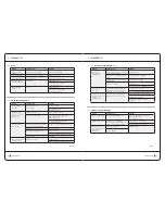
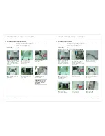
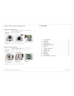
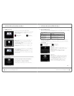
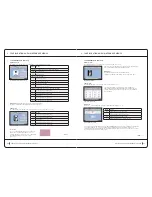
4.11 rePlacing tHe Front Panel (iHM)
Safety:
For safety reasons, the CELLU M6 safety operator or technician should not continue
when the machine is powered on or in 230V areas.
Unplug the power cord from the outlet.
required materials:
1 x T20 torx key
operating time:
20 min.
1)
Follow the instructions from step 1 to 4:
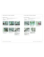
4.5 rePlacing tHe Panel adjuStMent Brake
reassembly:
Perform the operations in reverse to reassemble the new assembly.
note:
download the software update via the uSB key, if needed.
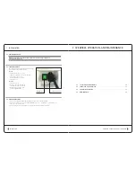
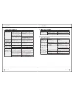
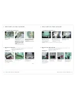
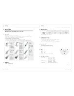
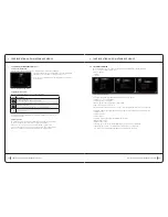
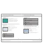
4.12 cHanging tHe Filter SenSor
Safety:
For safety reasons, the CELLU M6 safety operator or technician should not continue
when the machine is powered on or in 230V areas.
Unplug the power cord from the outlet.
required materials:
1 x T20 torx key
operating time:
15 min.
reassembly:
Perform the operations in reverse to reassemble the new assembly.
3)
Remove the sensor
clip, and remove
the O-ring.
do not touch the sensitive part of
the sensor to prevent damage.
1)
Remove the filter (see User Guide).
2)
Follow the instructions from step 1 to 6:
4.7 rePlacing tHe Filter HouSing
.
!
4 service sheets: structural components
service sheets: structural components
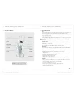
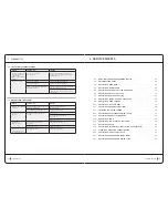
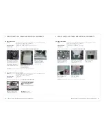
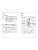
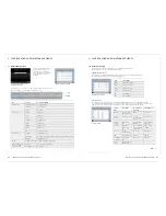
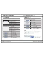
4.10 rePlacing a caStor WHeel
Safety:
For safety reasons, the CELLU M6 safety operator or technician should not continue
when the machine is powered on or in 230V areas.
Unplug the power cord from the outlet.
required materials:
1 x T20 torx key, 1 x T30 torx key, 1 x 18cm wooden dowel
operating time:
10 min.
1)
Raise and unclip to remove
the head storage tray..
2)
Unscrew the screw attached
to the housing (T20 Torx) and
take it out from the top.
4.9 rePlacing a Head SuPPort
Safety:
For safety reasons, the CELLU M6 safety operator or technician should not continue
when the machine is powered on or in 230V areas.
Unplug the power cord from the outlet.
required materials:
1 x T20 torx key
operating time:
5 min.
reassembly:
Perform the operations in reverse to reassemble the new assembly.
reassembly:
Perform
the operations in reverse
to reassemble the new
assembly.
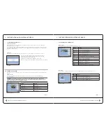
note:
Move the red
marker on the wheel
axis to the left, as shown
below. otherwise, the
brake lever will work
backwards.
3)
Unscrew the two
screws from the wheel to
pull it downward. Put the
dowel under the device
to stabilize it.
2)
Unscrew
one of the two
screws from the axel, and
slide the two pedals to
remove them.
1)
Unscrew the screws
attached to the cover
under the wheel legs
(3mm hex key, depending
on the version). Remove
the wheel covers.


