38
39
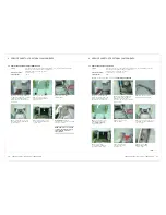
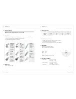
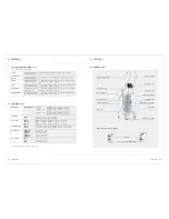
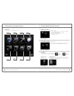
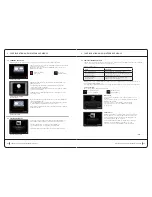
4 service sheets: electronic and electrical components
service sheets: electronic and electrical components
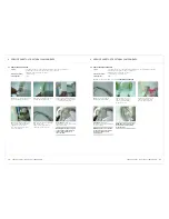
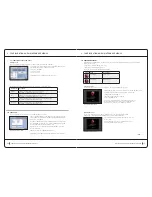
2)
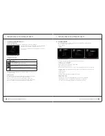
Remove the fan by pulling
its Richmo attachments,
cutting them, and removing
them, if necessary.
6)
Disconnect the fan’s
power cable, and then
remove the fan.
reassembly:
Perform the operations in reverse to reassemble the new assembly.
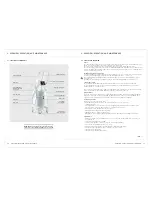
4.17 rePlacing tHe Fan
Safety:
For safety reasons, the CELLU M6 safety operator or technician should not continue
when the machine is powered on or in 230V areas.
Unplug the power cord from the outlet.
required materials:
1 x T20 torx key, 1 x cutting pliers, 1 x T3 hex key.
operating time:
25 min.
1)
Follow the instructions from step 1 to 3:
4.7 rePlacing tHe Filter HouSing
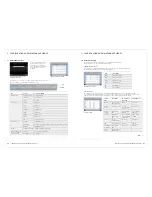
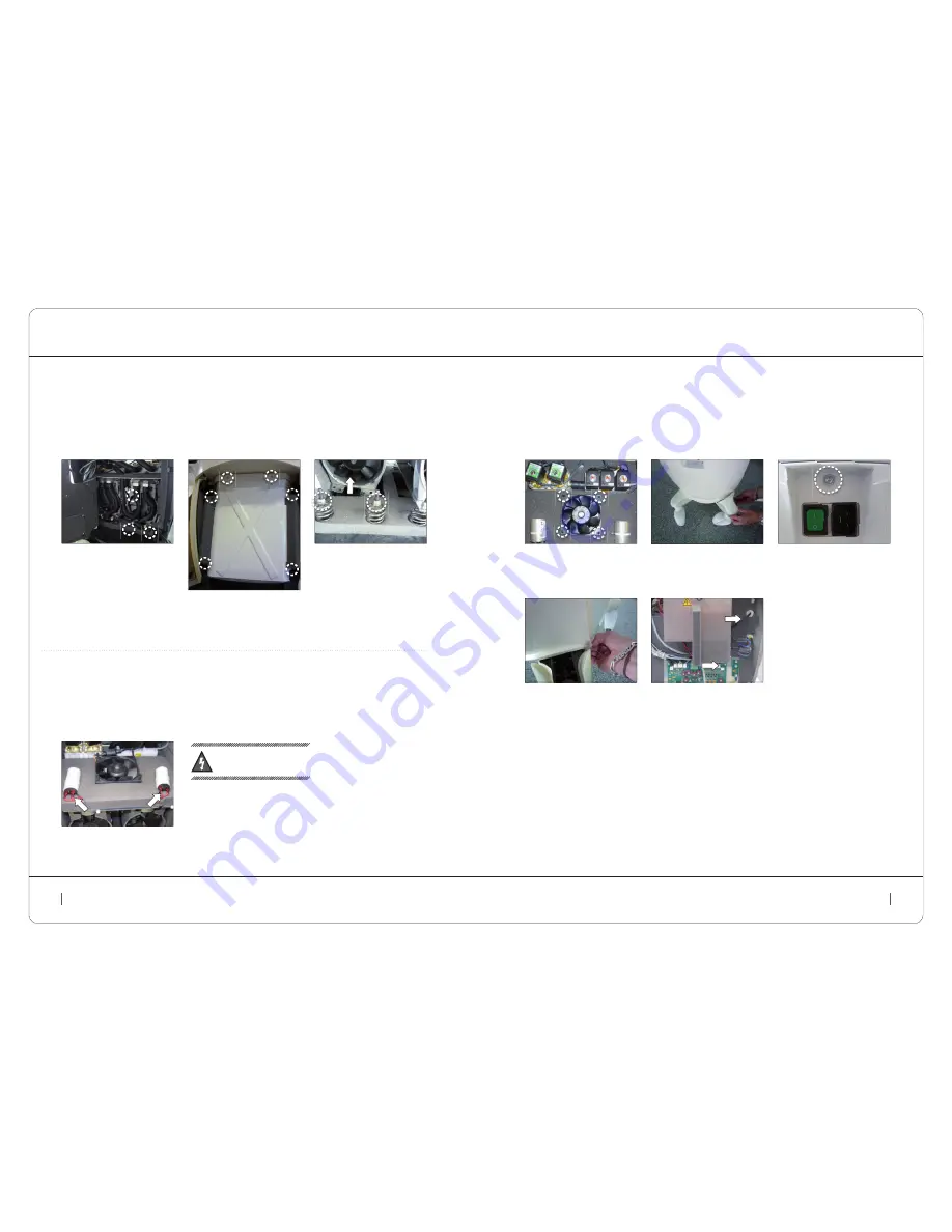
3)
Unscrew the screws attached
to the cover under the wheel
legs (3 mm hex key, depending
on the version).
Remove the wheel covers.
4)
Unscrew the locking
screws on the top
of the power socket.
5)
Unclip the rear cover by
firmly pulling downward,
and set it aside.
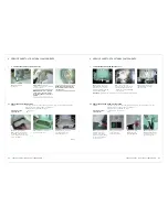
4 service sheets: electronic and electrical components
service sheets: electronic and electrical components
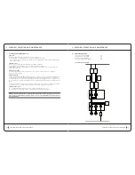
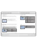
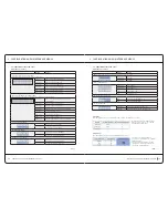
2)
Disconnect and remove the
condenser from its housing by
removing the plastic ties
4.16 rePlacing a PuMP StartuP caPicitor
Safety:
For safety reasons, the CELLU M6 safety operator or technician should not continue
when the machine is powered on or in 230V areas.
Unplug the power cord from the outlet.
required materials:
1 x T20 torx key.
operating time:
15 min.
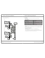
4.15 rePlacing a PuMP
Safety:
For safety reasons, the CELLU M6 safety operator or technician should not continue
when the machine is powered on or in 230V areas.
Unplug the power cord from the outlet.
required materials:
1 x T20 torx key, 2 x 10mm flat wrenches, 1 x 3mm hex key.
operating time:
30 min.
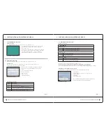
1)
Follow the instructions from step 1 to 4:
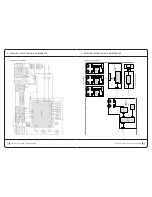
4.13 rePlacing tHe uniVerSal PoWer SuPPly
1)
Follow the instructions from step 1 to 3:
4.7 rePlacing tHe Filter HouSing
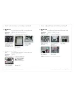
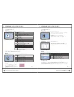
2)
Rotate the plate assembly to
the left, being careful not to pull
on the strands of cable.
Disconnect the suction inlet hose
and unscrew the two nuts on the
shock absorbers, holding the
locknuts (2x10mm flat wrenches).
3)
From the front: Unscrew
the six screws from the
base plate and remove it.
4)
Unscrew the two nuts
(2 10mm keys), holding the
shock-absorber locknuts,
and remove the pump from
the back of the unit.
reassembly:
Perform the operations in reverse to reassemble the new assembly.
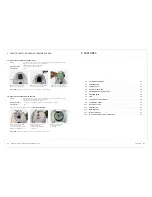
reassembly:
Perform the
operations in reverse to
reassemble the new assembly.
eLeCtRiC
SHock Warning:
discharge the condenser
before handling it.

