40
41
4 service sheets: electronic and electrical components
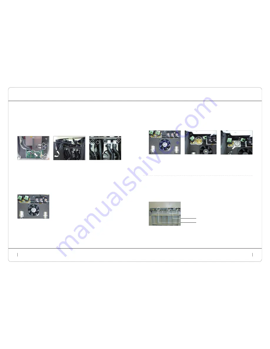
service sheets: electronic and electrical components
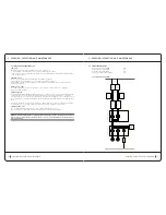
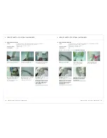
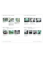
4.19 cleaning a Selection Solenoid ValVe
Safety:
For safety reasons, the CELLU M6 safety operator or technician should not continue
when the machine is powered on or in 230V areas.
Unplug the power cord from the outlet.
required materials:
1 x T20 torx key.
operating time:
10 min.
2)
Use the flat screwdriver to
remove the lock clip from the
solenoid coil to be cleaned.
3)
Unscrew the four screws from
the top assembly (T20 Torx) and
open the solenoid coil body. Pull
out the moving parts: membrane,
core, and compression spring.
4)
Dust off all of the parts,
and check that the O-ring
is correctly positioned..
1)
Follow the instructions from step 1 to 3:
4.7 rePlacing tHe Filter HouSing
reassembly:
Perform the operations in reverse to reassemble the new assembly.
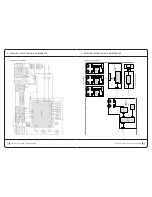
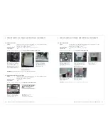
4.20 rePlacing a ligHt StriP circuit
Safety:
For safety reasons, the CELLU M6 safety operator or technician should not continue
when the machine is powered on or in 230V areas.
Unplug the power cord from the outlet.
required materials:
1 x T20 torx key, 1 x 3mm hex key.
operating time:
15 min.
2)
Disconnect the connector(s) (2 on
the left side and 1 on the right side)
and the shunt (identified by yellow
to the left and blue to the right).
1)
Follow the instructions from step 1 to 4:
4.8 rePlacing a Front, rear, or Side coVer
reassembly:
Perform the operations in reverse to reassemble the new assembly.
shunt
connectors
4 service sheets: electronic and electrical components
service sheets: electronic and electrical components
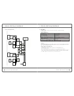
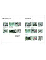
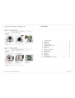
4.18 rePlacing a ValVe Block (regulation or Selection)
Safety:
For safety reasons, the CELLU M6 safety operator or technician should not continue
when the machine is powered on or in 230V areas.
Unplug the power cord from the outlet.
required materials:
1 x T20 torx key, 1 x 8mm flat wrench, 1 x 3mm hex key.
operating time:
30 min.
6)
Disconnect the interconnecting
hose and the clear silicon hose,
if replacing the regulation bar.
Remove the bar to be replaced.
4)
Rotate the plate assembly
to the left, being careful not
to pull on the strands of
cable. Disconnect the inlet
hoses on the solenoid valve
bar to be removed.
5)
Unscrew the screws from
the bar to be replaced from
below the plate (8mm flat key).
1)
Follow the instructions from step 1 to 3:
4.7 rePlacing tHe Filter HouSing
2)
Follow the instructions from step 1 to 3:
4.8 rePlacing a Front, rear, or Side coVer
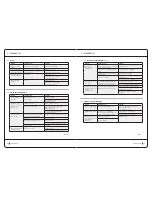
3)
Unscrew the four retaining
screws (T20 Torx), and then
disconnect:
The power cable from
•
the control card (1)
The two (2) pump power
•
cables, marking their positions.
Unscrew the locks (3mm flat
screwdriver).
Disconnect the pumps from
•
the grounding (3) (If needed,
depending on the version).
1
2
3
reassembly:
Perform the operations in reverse to reassemble the new assembly.

