background image

58

59

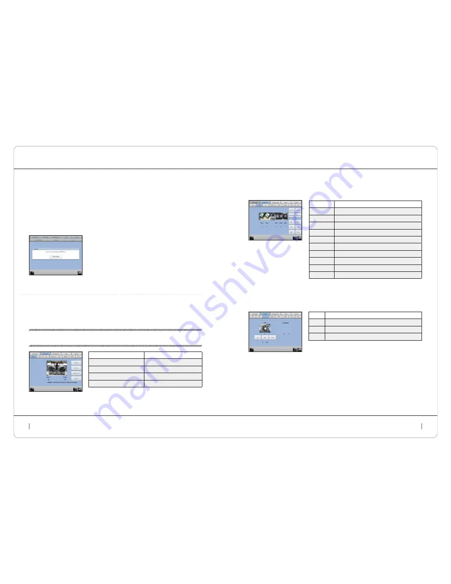
6.9b  unitary teStS Screen (cont.)

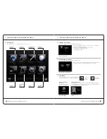
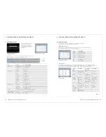
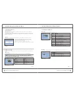
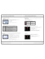
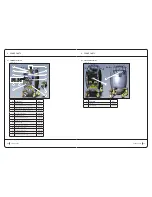
Valves screen

Each solenoid valve can be tested individually from this screen

Fan screen 

The measurements from the temperature sensor on the regulation board can be checked from this screen.

configuration and maintenance menus

6  configuration and maintenance menus

Button

action

EVS1 Close

Close Selection Solenoid valve 1

EVS2 Close

Close Selection Solenoid valve 2

EVP1 -

Close Pump Solenoid valve 1

EVP2 -

Close Pump Solenoid valve 2

EVPA -

Close Atmospheric pressure solenoid valve

EVS1 Open

Open Selection Solenoid valve 1

EVS2 Open

Open Selection Solenoid valve 2

EVP1 +

Open Pump Solenoid valve 1

EVP2 +

Open Pump Solenoid valve 2

EVPA +

Open Atmospheric pressure solenoid valve

Button

action

0 %

Fan speed set at 0%: 900rpm (±10%)

50 %

Fan speed set at 50%: 2250rpm (±10%)

100 %

Fan speed set at 100%: 3600rpm (±10%)

solenoid valves test screen

fan tests screen

cont .


>

configuration and maintenance menus

6  configuration and maintenance menus

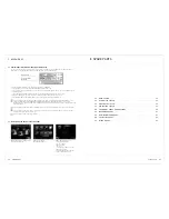
6.9a  MacHine State taB (cont.)

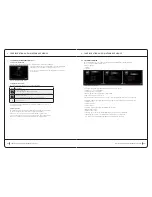
counters screen (cont.)

Memory updates of the current usage times is variable. A variation of 1 to 2 minutes exists for the components  

and up to 5 minutes for the IHM.
For example, pressing the adapter button prompts an increase of the ‘button press’ counter. The new counter value 

is not immediately visible after refreshing the screen. The updated value will be displayed after the component has 

updated the counter memory.

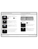
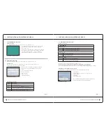
log screen

The logs event history, application and error information etc. can be copied to a USB key for future reference.

Once the ‘Start Copy’ button is pressed, the insertion of a USB key is 

requested. Once inserted a file is written to the USB key containing  

all the logs under the following name type:

'LpgCont.Log <SN Machine ><SN HMI><Date-Heure>'

When the file copy is completed a prompt is displayed to remove the USB key.

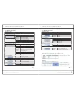
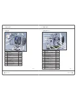
6.9b  unitary teStS Screen

The unitary test screens allow simple tests to be carried out on each component. Eight screens are available under 

this tab:

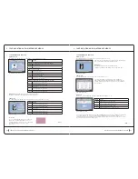
Pumps screens

The correct function of pumps can be checked from this screen. Each pump can be started individually  

or simultaneously. 

Attention: 

the start-up of the pumps is uncontrolled – both the Pump solenoid valves (eVPs) and the 

Selection solenoid valve (eVS) or atmospheric Pressure solenoid valve (eVPa) must be opened to start the 

pumps. the pumps can not be started under constraint.

Button

action

Pump 1 On

Start Pump 1

Pump 2 On

Start Pump 2

Pumps 1 & 2 On

Start Pumps 1 & 2

Pumps Off

Stop Pumps

log screen

pump test screen

cont .


>

Summary of Contents for Cellu M6

Page 1: ...integral maintenance manual...

Page 2: ...service sheets 25 5 features 43 6 Configuration and maintenance menus 49 7 Appendices 59 8 spare parts 61 1621 GB LPG Systems Public company with share capital of 2 000 000 euros Siren 335 183 836 RCS...

Page 3: ...4 5 information 1 information 1 1 Warnings 6 1 2 Product Storage Conditions 7 1 3 electrical danger 8 1 4 off on 8 1 5 usage precautions 8...

Page 4: ...ies in any form whatsoever without the express permission of LPG Systems law dated 03 11 1997 What are the conditions for using the Cellu M6 The Cellu M6 should only be used by a qualified professiona...

Page 5: ...on Confirm that the switch is at 0 Completely unwind the machine s power cord Connect the cord first to the machine and then to the outlet Set the switch to 1 Turn off Set the switch to 0 Disconnect t...

Page 6: ...ick up accumulated desquamation and protects the vacuum control assembly from foreign bodies Their use time is a 40 hours maximum Their clogging rate is monitored by the control electronics only in th...

Page 7: ...er that the device is connected to the network that it is receiving power and that it is ready to operate Roll Massage Head The motorized massage head adds two moving rollers to the suction Their func...

Page 8: ...2 Overview Operation and Maintenance 3 a Head Connection Diagram Auxiliary head adapter Keymodule Ergodrive head TR50 four Integral I only Overview Operation and Maintenance 2 Overview Operation and...

Page 9: ...ive sponges When cleaning the parts of the machine that come into contact with patients always use wipes For the inside of the head storage drawer and tray use a fine tipped vacuum cleaner to remove d...

Page 10: ...agnostics 3 1 noises 20 3 2 Equipment Performance 20 3 3 General Critical Problems 21 3 4 General Unexpected Problems 23 3 5 Control Screen Problems 23 3 6 Critical Massage Head Problems 24 3 7 Minor...

Page 11: ...reen on the panel voltage indicator and rear green indicator lit Panel fails to start up Replace the panel No back lighting diagnostics 3 diagnostics 3 1 noises 3 2 Equipment Performance Problem Proba...

Page 12: ...dicator on the panel is lit If it is not replace the power unit The machine is not plugged in properly If the cord is too long or to short it creates too much resistance Plug it in and switch on the p...

Page 13: ...e Clean the roller Check the brake and reposition it after removal Replace the roller Head storage drawer or filter access locked A foreign object is blocking the drawer Remove the foreign object A sl...

Page 14: ...key 1 x T30 torx key 4 7 Replacing the Filter Housing 1 x T20 torx key 4 8 Replacing a Front Rear or Side Cover 1 x T20 torx key 1 x T3 hex key 4 9 Replacing the Head Support 1 x T20 torx key 4 10 Rep...

Page 15: ...ow the instructions from step 1 to 4 4 3 rePlacing a Head HoSe 4 service sheets structural components service sheets structural components 4 3 rePlacing a Head HoSe Safety For safety reasons the CELLU...

Page 16: ...screws from the rear cover of the panel tilt the panel down to remove the cover cont 9 Unscrew T30 Torx and remove the both movable arms 10 Unscrew the two bases right and left from the frame 4 servic...

Page 17: ...U M6 safety operator or technician should not continue when the machine is powered on or in 230V areas Unplug the power cord from the outlet required materials 1 x T20 torx key 1 x T3 hex key operatin...

Page 18: ...eets structural components service sheets structural components 4 10 rePlacing a caStor WHeel Safety For safety reasons the CELLU M6 safety operator or technician should not continue when the machine...

Page 19: ...and electrical components 1 Unscrew the screws attached to the cover under the wheel legs 3mm hex key depending on the version Remove the wheel covers 4 Unscrew the four retaining screws T20 Torx and...

Page 20: ...4 16 rePlacing a PuMP StartuP caPicitor Safety For safety reasons the CELLU M6 safety operator or technician should not continue when the machine is powered on or in 230V areas Unplug the power cord...

Page 21: ...Follow the instructions from step 1 to 4 4 8 rePlacing a Front rear or Side coVer reassembly Perform the operations in reverse to reassemble the new assembly shunt connectors 4 service sheets electron...

Page 22: ...sconnect the two cables and remove the panel assembly 9 Remove the lower lid Remove the rotating mechanism 4 21 rePlacing tHe ergodriVe Front Panel Safety For safety reasons the CELLU M6 safety operat...

Page 23: ...e Class IIa per rule 9 of 93 42 EC MDD Equipment made of a vacuum pump generator and a pneumatic system actuator controlled by a 16 bit microprocessor pilot and a 100 240V 50 60Hz universal power supp...

Page 24: ...ce 1 5 to 5 3 cm2 tMl 30 Width of flap 30 mm Variable care surface 2 5 to 8 6 cm2 auxiliary Heads tr 30 Rollers 14 mm L 30 mm Variable care surface 5 5 to 7 3 cm2 tr 15 Rollers 10 mm L 15 mm Variable...

Page 25: ...mpurity filtration 5 m Product identification by individual serial number located on the identification label Product traceability by individual manufacturer sheet INPI registered model Institut Natio...

Page 26: ...n allows acces to screens for the adjustment of the light band and touchscreen brightness via two buttons Touchscreen brightness adjustment Two buttons increase or decrease screen brightness Light ban...

Page 27: ...nd use of the unit is allowed Lock function active and unit blocked The limited period of use has been reached and use of the unit is blocked cont manual code input screen automatic code input screen...

Page 28: ...6 7 Periodic locking function cont Security code confirmation Once the code is input either manually or automatically a confirmation is displayed The new period of use dates corresponding to the code...

Page 29: ...wer supplied to corresponding component Power supply stopped Control Suction regulation time Suction on Suction off Led LED usage time LED on LED off FrontMotor RearMotor Roller usage time Roller on R...

Page 30: ...For example pressing the adapter button prompts an increase of the button press counter The new counter value is not immediately visible after refreshing the screen The updated value will be displayed...

Page 31: ...0 Diminution du retro eclairage de 10 Max Reglage du retro eclairage a 100 Augmentation du retro eclairage de 10 adapter test screen Light band test screen touchscreen test screen cont Configuration a...

Page 32: ...cont Configuration and maintenance menus 6 Configuration and maintenance menus 6 9b Unitary tests tab cont Hmi Screen cont The calibration button allows access to the touch screen calibration screen...

Page 33: ...0 rpm 10 cont Configuration and maintenance menus 6 Configuration and maintenance menus Button Action Selection solenoid valve adjustment These solenoid valves allow selection of Arm 1 Arm 2 or both O...

Page 34: ...tab The setup tab has one maintenance screen named Components Setup This screen allows updates of components connected to the machine These updates are contained in the update package loaded during t...

Page 35: ...belle du defaut Description Niveau de l erreur FlyBack PFC Variator Controller AccFailure Start up autotest fault accelerometer Warning SDRAMFailure Start up autotest fault SDRAM Warning DataFlashFail...

Page 36: ...70 71 appendices 7 Appendices 7 1 Device Identification and Identification Module 72 7 2 Identifying the Device using the Panel 72...

Page 37: ...The letter indicates the tyear the device was manufactured Z 2009 A 2010 B 2011 etc The two digits indicate the production month 01 January 02 February 03 March etc This icon indicates that the unit w...

Page 38: ...ht cover 1011631 11 Back filters compartment cover 1011387 12 Upper sheet 1011572 13 Front sheet 1011384 14 Ejot Easy boss nuts pack X10 1012774 cont 2 8 7 6 5 4 3 1 9 10 11 12 13 cont spare parts 8 s...

Page 39: ...376 Regulation board Front panel plug wire 1012374 Regulation board Head plug wire 1012378 Regulation board sensor plug wire Regulation board light board wire 1012375 Integral front panel wire adaptor...

Page 40: ...tion subset hose 1011686 3 Right pump Regulation subset hose 1011687 4 Integral selection valve subset 1012775 Selection valve body 1000199 5 Regulation block 1012776 6 SelectValve Right filter hose 1...

Page 41: ...ion Code Ergodrive KM80 1011552 Ergo KM80 tightness flaps X6 1013144 Ergodrive KM70 1011530 Ergo KM70 tightness flaps X6 1013261 Ergodrive KM50 1011444 Ergo KM50 tightness flaps X6 1013260 1 4 2 3 con...

Page 42: ...ad 8 7 non motorized heads TR30 TR15 8 8 facial lift heads TML30 TML20 TML10 Designation Code TR50 1011374 TR 50 Flaps and cover subset 1013144 ID Designation Code 1 TR30 1011791 2 TR15 1011790 1 2 1...

Reviews: