62
63
configuration and maintenance menus
6 configuration and maintenance menus
>
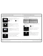
6.9c Functional teStS taB (cont.)
Vacuum screen (cont.)
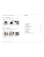
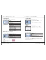
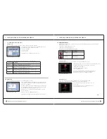
functional tests screen
Button
action
ARM SELECTION
1
Select Arm 1 to regulate the vacuum pressure
2
Select Arm 2 to regulate the vacuum pressure
PUMP START UP
Start
Start the regulation pumps
Stop
Stop the regulation pumps
PRESSURE SETTING
-
Decrease the pressure setting by 50 mBar
+
Increase the pressure setting by 50 mBar
The arm selection can only be changed when the pumps are off.
The pressure control is carried out by the external sensor (External Arm 1 or External Arm 2)
The pressure value measured should correspond to the specified pressure setting by ±10%
This test can only be carried out if the arm hose is in correct working condition, without blockage or leakage.
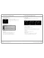
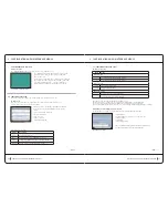
Button box screen (according to software version)
The ‘button box’ screen allows testing of various functions simultaneously. These include:
Solenoid valves
•
Setting parameters (frequency, cycle rate, pressure)
•
Pump pressure
•
Light band
•
Fan and temperature
•
This screen displays a large quantity of buttons and information.
Each part is described in full on the following pages.
cont .
>
configuration and maintenance menus
6 configuration and maintenance menus
>
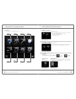
6.9b unitary teStS taB (cont.)
Hmi Screen (cont.)
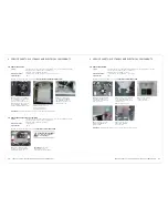
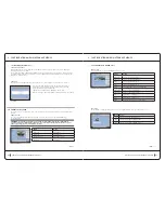
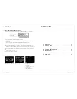
The calibration button allows access to the touch-screen calibration screen
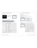
6.9c Functional teStS taB
Functional tests on the unit may be carried out from these maintenance screens.
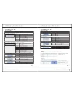
Vacuum screen
The correct function of pressure regulation for each arm can be checked from this screen.
It can be used to detect faulty sensors or leakages.
The pressure values are limited at approximately 900mBar
for the external sensors and 1150 mBar for the internal
sensors.
This screen is divided into 4 parts
Measurements table
•
Arm selection
•
Pumps start-up
•
Regulation command
•
touchscreen calibration screen
regulation tests screen
column
description
Sensor
Pressure sensor used
ADC
Value returned by the Analoque/Digital Converter
Voltage
Voltage corresponding to the value returned by the ADC
Vacuum
Vacuum pressure corresponding to the voltage
Measurement results table
cont .
>
The calibration is carried out by pressing for a few seconds
(preferably with a stylus type object) the point indicated
onscreen by a cross.
Four points are required for correct calibration. The calibration
of each point has a time limit (the remaining time is indicated
in the bar at the bottom of the screen). The calibration is
automatically cancelled when the time limit is exceeded.


