66
67
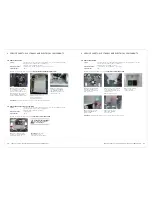
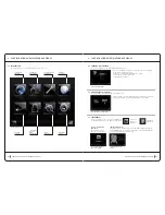
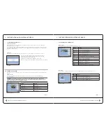
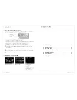
6.10 error ManageMent
Monitoring of all components is carried-out from the start-up of the software. Different levels of error or fault
may be encountered:
Critical level (potential danger to the user)
•
Warning level (no danger to the user)
•
These two error levels are displayed in the toolbar:
critical level error
In the event of a Critical Level error occuring, an error pop-up is displayed on screen:
This pop-up lists all detected errors (of both ‘critical’ and 'warning’ levels)
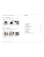
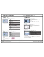
All components are automatically switched to ‘sleep’ mode:
Pumps and suction stopped
•
Massage heads and rollers stopped
•
Fan at minimum speed
•
Pressing the confirm button closes the pop-up whilst the icon
in the toolbar remains even if the error is no longer present.
All critical level errors are conserved in this manner.
Warning level error
In the event of a Warning Level error occurring, an error icon is displayed in the toolbar.
A pop-up does not appear and the components are not placed in ‘sleep’ mode
The error details can be viewed by pressing the error icon
in the toolbar.
Once the Warning level error is cleared from the screen,
it is also removed from the fault list
configuration and maintenance menus
6 configuration and maintenance menus
Button
action
description
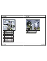
Error display
Critical level
Error display
Warning level
critical level error pop-up
warning level error display
cont .
>
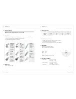
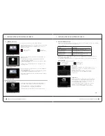
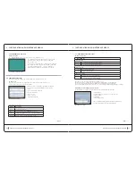
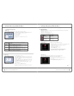
6.9d SetuP taB
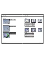
The ‘setup’ tab has one maintenance screen, named ‘Components Setup’
This screen allows updates of components connected to the machine.
These updates are contained in the update package loaded during the
last touch-screen update.
To update a component the file corresponding to the component must
be selected from the table (the selected line is displayed in grey) and
the ‘Load Application’ button must be pressed.
Attention: in the case of a massage head or Keymodule, these must
be connected to Arm 1.
Components cannot be updated simultaneously.
The progress of the update is displayed in the bar next to the button.
>
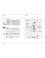
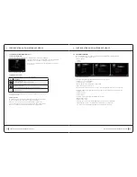
6.9c Functional teStS taB (cont.)
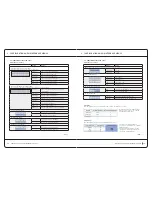
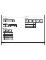
Burning screen
This screen allows testing of temperature endurance under unfavourable conditions.
Pressing the ‘start’ button launches the unfavourable conditions test.
The start button becomes ‘stop’ once launched.
Pressure: 900 mBar
•
Frequency: 4 Hzz
•
Cycle rate: 40 %
•
An automatic timer records the duration of the test.
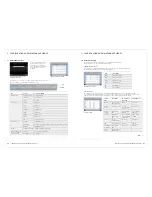
The following table describes the sensors used to calculate current temperature
configuration and maintenance menus
6 configuration and maintenance menus
Sensor name
description
FlyBack
Temperature measured on the 24V power supply
(maximum recommended temperature: 90°C)
PFC
Temperature measured on the power factor corrector
(maximum recommended temperature: 90°C)
Variator
Temperature measured on the power inverter of the power supply
(maximum recommended temperature: 85°C)
Controller
Temperature measured on the regulation board
(maximum recommended temperature: 70°C)
component updates screen
functional endurance tests screen

