10
11
overview, operation, and maintenance
2 overview, operation, and maintenance
2.2 PrinciPle oF oPeration
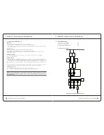
Power
The “universal power supply” block receives its power from the mains. A 24v DC is generated to power the entire
device, and a 230v AC 50-60Hz is generated to power the 2 vacuum pumps.
The 24v DC output voltage powers the control board, the light strip, and the voltage indicator lights.
The 230v AC voltage is generated on two connectors independently powering each pump. It has the ability to stop
any defective pump and use the BUS CAN to show a message on the panel. This power is protected against short
circuits, overloads, and overheating.
Vacuum Pump, control, and Selection
Each vacuum pump uses proportional and selection solenoid valves to create a suction in the selected treatment
chamber. These pumps are powered by 230v 50/60Hz, depending on the device’s suction need.
This is floating voltage, grounded only indirectly and presenting a risk of electric shock from physical contact
when powered.
The pumps are equipped with circuit breakers in the event of overheating, allowing for an automatic reset.
control and Selection
The resulting suction modulated by the proportional solenoid valves is either continuous or sequential,
as controlled by the user. The suction is constantly controlled by the control board, which receives pressure
information from each filter box sensor.
The suction is directed to either the left (#1) or the right (#2) massage head by one of the two selection solenoid
valves controlled by the control board. Both heads cannot be activated at the same time.
Head air Filters
These two identical filters, with quick access through the sliding back door, pick up accumulated desquamation
and protects the vacuum control assembly from foreign bodies. Their use time is a 40 hours maximum. Their
clogging rate is monitored by the control electronics only in the event of premature clogging.
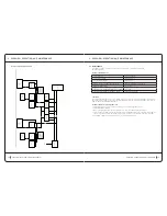
Pc touch Screen Panel
The touch screen has a user interface for:
Informing the user about how the machine is working (machine settings, chosen cycle,
•
needed maintenance, etc).
Controlling treatment cycles on the machine by selecting programs or modifications. The computer panel
•
is the device’s master system, which controls every component connected to it.
Controlling the control board for all of its functionalities.
•
Ordering the power supply to activate the pumps.
•
Updating the device’s software via a USB stick.
•
Managing time meters: Registering operating time of the machine and of the left and right circuit filters.
•
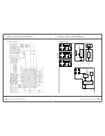
control Board
Based on the information received by the filter pressure sensors and the information from the PC panel, the
•
control board can:
Calculate the pneumatic control settings.
•
Control all of the pneumatic and electrical system actuators (EVP and EVS).
•
Detect the level of clogging in the filters, if excessive.
•
Transmit communication between the heads and panel. (BUS CAN 1 and CAN 2)
•
Develop the 9v DC required by the device’s low-power electronic circuits.
•
Control the lateral light strips.
•
Control the fan in the pump compartment.
•
!
cont .
>
overview, operation, and maintenance
2 overview, operation, and maintenance
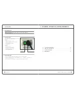
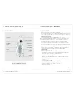
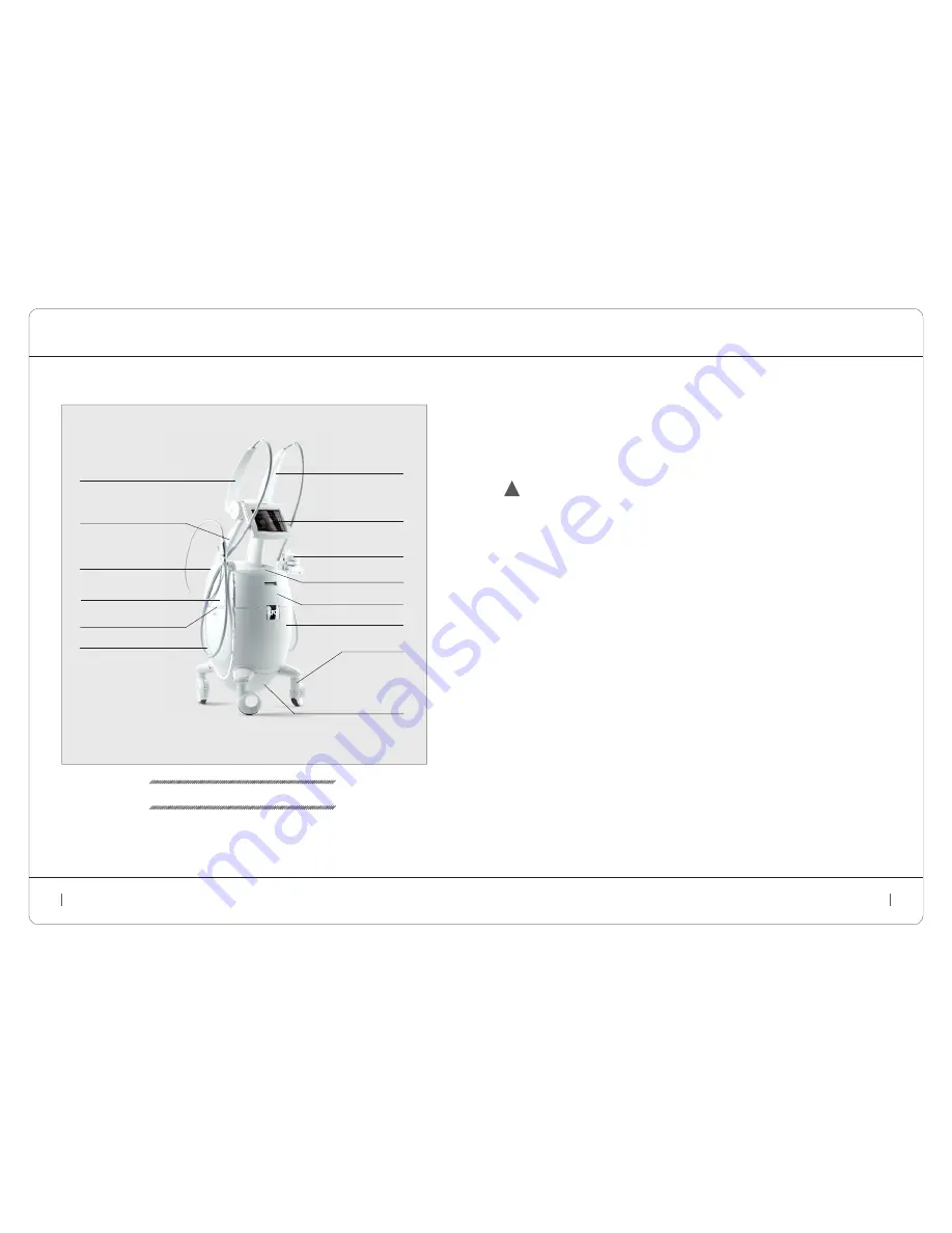
2.1 location oF coMPonentS
note:
naming convention for the sides of the machine:
the machine side is designated from the user’s position.
light strip
left side cover
back cover
left movable arm
right movable arm
adjustable touch screen panel
head and hose storage
head storage drawer
front cover
bottom cover
with ventilation
head storage tray
frame arm
caster wheel
with locking
cable winder with
air inlet and filter
access door

