1 3
1 2
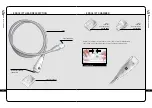
FIG. 2
FIG. 1
FIG. 3
FIG. 4
FIG. 5
>
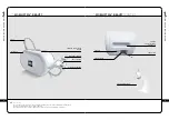
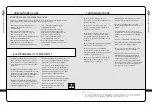
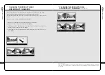
INSTRUCTIONS FOR CONNECTING THE HOSE
• To connect the hose, proceed as indicated below:
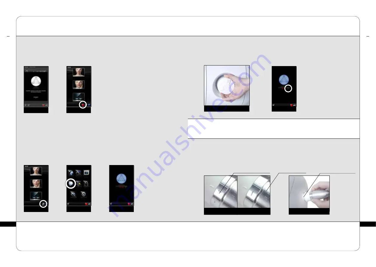
• Position the locking ring in the locked position
(fig. 1).
• Position the end of the hose so that the hose key is lined-up with the key slot of the treatment
head connection
(fig. 2).
• Push the hose into the treatment head connection until it clicks into place.
FIG. 1
UNLOCKED
LOCKED
FIG. 6
FIG. 7
FIG. 2
HOSE RETAINER KEY
LOCKING RING
ORNAMENTAL RING
MAINTENANCE
4
>
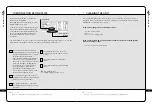
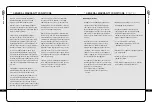
REPLACING THE FILTER CARTRIDGE
Your device contains a filter cartridge.
These components guarantee the efficiency of your unit and prolong its useful life.
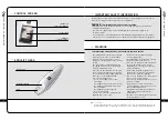
Ensure that they are changed as soon as the command screen displays one of these
messages
(fig 1-2) :
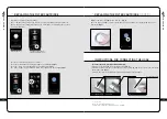
Access the ‘filter change’ menu as follows :
Select the ‘maintenance’ menu by pressing the icon indicated
(fig. 3).
Select the ‘filter’ menu by pressing the icon indicated
(fig. 4).
The ‘filter change’ screen indicates which filter requires to be changed
(fig. 5).
ICON INDICATING A FILTER
CHANGE IS REQUIRED (FIG. 2).
WARNING MESSAGE
Never use your device without a filter.
Turn the device off before replacing your filter cartridge.
≥
A T T E N T I O N
>
REPLACING THE FILTER CARTRIDGE
(CONT’D)
MAINTENANCE
4
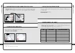
Replace the filter cartridge with a new one.
(fig. 6)
Once the filter cartridge is replaced, the filter meter should be reset by pressing the icon as
indicated :
(fig. 7).

