background image

Computer-controlled functions

ProtoMat M60

                                                                                                                                                                            13

   4.0  Computer-controlled functions 

4.1  Connection to a PC 

The LPKF 

ProtoMat

 M60 has two serial interfaces. The first (SERIAL 1) 

is the INPUT to the system and is used for connection to the controlling 

computer (PC). The second interface (SERIAL 2) is an OUTPUT and is 

provided for future applications.

The LPKF 

ProtoMat

 M60 control unit's SERIAL 1 is connected to a serial 

interface on the computer with the RS232 cable supplied. 

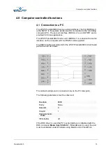
The RS232 cable (null modem) for the LPKF 

ProtoMat

 M60 circuit board 

plotter is wired as follows: 

The cable shield ground is connected only on the PC side (port). 

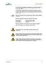
The following parameters must be observed:

If the DOS driver is used the PC's serial interface is initialized with the 

DOS command 

Mode Com1:96,N,8,1

. If 

BoardMaster

 is used, the port 

must be initialized under Windows using Main/Control Panel/Ports.

Baudrate

9600 

Parity

None

Datenbit

8

Stopbit

1

Hardwarehand-

shake

FIFO-Buffer

off

Summary of Contents for ProtoMat M60

Page 1: ...Manual ProtoMat M60 English version 1 0 LPKF Laser Electronics AG Osteriede 7 D 30827 Garbsen Telefon 49 51 31 70 95 0 Telefax 49 51 31 70 95 90 eMail lpkf lpkf de Homepage http www lpkf de...

Page 2: ...oval of LPKF AG Right to make modifications reserved No liability is accepted for the content In particular we accept no liability for damage caused by information given information absent or erroneou...

Page 3: ...the duty of the system owner to care for and plan these measures as well as to control their execution The owner especially has to ensure that the system is only used as directed the system is only op...

Page 4: ...ortant information Illustrations are numbered Example Fig 5 Prompts for actions are identified with an arrow Italic sections are used to indicate the reactions consequent on an action Words printed in...

Page 5: ...ds Base material Circuit board material coated with copper foil Solder foil special foil for cutting aperatures for the connections to be soldered BoardMaster Machine control software CurcuitCAM Softw...

Page 6: ...r borne sound 11 3 4 Installation 12 4 0 Computer controlled functions 13 4 1 Connection to a PC 13 4 2 Machine orientation 14 4 3 Displays and connections 15 4 4 Use of BoardMaster 16 5 0 Setup 17 5...

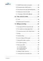
Page 7: ...Milling and drilling 28 7 1 Securing the PCB on the machine bed 28 7 2 The mechanical working depth limiter 29 7 3 Functional elements on the mill drill head 30 7 4 Drilling 31 7 5 Isolation milling 3...

Page 8: ...4 Serial port SERIAL 2 44 8 5 Motor connection 44 8 6 Mill head connection 45 8 7 EPROMs 45 8 8 Fuses commuting the device voltage 45 8 9 The LPKF ProtoMat M60 Commands 48 8 9 1 Command structure 48...

Page 9: ...tool into the clamping device as far as it will go Never operate the control PC simultaneously when working with the device Operator with longer hair must wear a hair net If you modify the equipment y...

Page 10: ...for the LPKF ProtoMat M60 is controlled from the serial port of a PC In order to make any guarantee claims if necessary it is absolutely vital to follow the instructions of this manual before putting...

Page 11: ...ssories can be supplied for the LPKF ProtoMat M60 Vacuum system with fine filter The fine filter is essential in particular when handling materials containing glass fiber such as for FR4 base material...

Page 12: ...properly Set up the circuit board plotter so that the connecting cables to the electronic unit can move freely Connect the LPKF ProtoMat M60 to the computer with the null modem cable supplied with th...

Page 13: ...SERIAL 1 is connected to a serial interface on the computer with the RS232 cable supplied The RS232 cable null modem for the LPKF ProtoMat M60 circuit board plotter is wired as follows The cable shiel...

Page 14: ...ea of movement 1 PAUSE position The machine will move to this point to load or turn the material to be machined 2 HOME position This is the relative 0 0 position and MUST lie on the machine mirror X a...

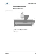
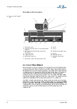
Page 15: ...ProtoMat M60 15 4 3 Displays and connections Description of the front panel fig 3 Front LPKF ProtoMat M60 1 Operating display of the integrated machine control SMCU 2 X motor 3 High speedcycle spindle...

Page 16: ...ditional capability such as step and repeat move rotate etc All LPKF circuit board plotters are driven via an asynchronous interface RS232C In the case of the LPKF ProtoMat M60 it is operated at 9600...

Page 17: ...rt the BoardMaster program If for some reason it should be necessary to switch the machine off and on again then change to the MACHINE SETTINGS window of the BoardMaster program and click on OK Throug...

Page 18: ...ping back into the normal position by themselves Caution Only operate the spindel with the vacuum cleaner switched on Note During set up take note that the bearings of the high speedcycle spindle have...

Page 19: ...serial interface used is set to 9600 baud 8 data bits 1 stop bit no parity bit and hardware handshake and FiFO buffer off Also check that CHANNEL and the correct interface have been selected in BoardM...

Page 20: ...e home position needs to be programmed on new equipment and when the system has been moved The HOME position of the LPKF ProtoMat M60 must be precisely on the mirror X axis the two pin system with the...

Page 21: ...l a hole at the HOME position with a 0 7 mm drill Move the mill drill head to the PAUSE position Turn the base material around about the X axis Move to the HOME position move to the tool change positi...

Page 22: ...n diameter so that the distance between the base plate and the drill point is about 0 5 mm Under the base material you can put a 0 5 mm thick base This is the only time a tool is not inserted into the...

Page 23: ...tch on the vacuum system during machining Move to the PAUSE position using BoardMaster GO TO PAUSE Fix the base material using alignment pins as described in the section Securing the PCB on the machin...

Page 24: ...tter and with the arrow keys move over the base material but not over the project in BoardMaster Set the step size manually approx 10 mm Switch on the milling drilling motor Move down the raise lower...

Page 25: ...l insertion and removal 1 Universal Cutter for milling of isolation canals and to the front panel engraving of 0 2 0 5 mm according to depth setting length 36 mm 2 Micro Cutter for milling isolation c...

Page 26: ...of smaller pads Normally a total thickness of 1 5 mm and a Cu thickness of 35 m are used With 17 m material even fine milling channels can be engraved at a higher packing density For galvanically thr...

Page 27: ...ter 0 8 mm Material supplied by LPKF and suitable for machining FR3 material engraving drilling milling FR4 material engraving drilling milling Engraving film engraving Material suitable for machining...

Page 28: ...not have to be moved by more than 10 mm as otherwise the two pin system precision decreases Now secure the base material in position with drafting tape masking tape is not recommended because it leave...

Page 29: ...own within certain limits by the working depth limiter The head is lowered with a solenoid and raised with a spring fig 9 The LPKF ProtoMat M60 working depth limiter Milling depth is set by adjusting...

Page 30: ...cle spindle 2 pneumatic cylinder 8 High speedcycle spindle 3 Adjustment bottom head stop Attention Do not move 9 Holding block 4 Working depth limiter 10 Adjustment screw for working depth limiter 5 K...

Page 31: ...g nut can be used to make this adjustment An excessive lowering speed can result in burrs particularly where holes have a small diameter Only one PCB can be drilled at a time It is not possible to sta...

Page 32: ...degreaser for electronic components so that milling dust can be removed more easily by the extractor The milling depth must be set as large deep as possible in all cases If only the extreme milling cu...

Page 33: ...Contour milling in PCB material fig 15 Contour cutter 1 two edged cutter 2 The speed of movement has to be lowered for contour milling This may differ from material to material Only use special conto...

Page 34: ...or switched on Always use the superfine filter Danger When machining some materials e g teflon hazardous gases might be produced 7 7 Milling wide isolation channels fig 16 Double chamfered cutter Wide...

Page 35: ...ent adhesive tape which must not stretch to form an air seal There must not be any air bubbles between the film and the base The milling depth can now be set at the film edge It can be checked by mill...

Page 36: ...ructions on the color container Important the liquid must not get onto the back of the film as it cannot then be removed from it The color is also difficult to remove from other surfaces fabrics skin...

Page 37: ...ked boards as well as mechanical parts The lower oin of the micrometer screw serves as a stop and prevents the further lowering of the machine head 7 12 Cleaning the PCB Before components are mounted...

Page 38: ...lf works in a clockwise direction The standard postprocessing is already designed for this CircuitCAM allows the user to select the direction of the milling tool and therefor mirroring prior to isolat...

Page 39: ...PCB and the drilling base Drills can also break if the tool is too high above the material By moving the adjustment valves of the pneumatic stroke the lowering speed can be adjusted This prevents the...

Page 40: ...1 Maintenance Keep spindles clean In rooms with a high air humidity wipe down with a lightly oiled cloth from time to time Keep transport spindles oiled and clean Caution Do not oil bearings Please u...

Page 41: ...the brush provided Caution Only lightly lubricate the thread of the working depth limiter with graphite or Teflon After cleaning the working depth limiter is refitted following the procedure in revers...

Page 42: ...s well lubricated 8 2 1 Carriage guide wipers of the X axis The wipers 4 in total are located on both sides of the carriage both in front of and behind the guide cheeks A hole has been drilled on the...

Page 43: ...cause the output stages of the stepping motors to be damaged by induced voltage 8 3 Serial port SERIAL 1 The serial data channel SERIAL 1 is an RS 232 C standard interface with photo diode decoupling...

Page 44: ...per axis via a 15 pole SUB D plug If the limit switch is actuated any further axis movement in the direction of the limit switch is immediately blocked The position of the sockets is described in the...

Page 45: ...page 45 and change the EPROMs ensuring that the EPROMs are correctly aligned and positioned Use only an IC extractor to remove the EPROMs as otherwise the contacts of the mounting might be damaged Wh...

Page 46: ...s loosen screws 1 2 3 and 4 at the bottom of the device and then remove the cable connections between the mechanical part and the control unit fig 23 Position of screws for removing the electronics fr...

Page 47: ...aud rate setting with default setting B Transformer J Power packs C Transformer connection K Processor D Power pack for mill drill head L EPROM L E Power pack Z axis not used M EPROM H F Power pack Y...

Page 48: ...he machine is 0 0079375mm This is a different resolution than that of standard HP GL plotters Therefore the output is scaled down when original commands are used The syntax The SMCU expects a separato...

Page 49: ...nts lying diagonally to each other The first corner point is determined by the current position and the second by the relative coordinate x y IN Initialize Changes the control unit to the same status...

Page 50: ...the tool with number n 8 9 3 Special commands All special commands begin with the symbol and their syntax is otherwise like that for HP GL standard commands AS a Acceleration Set Defines a new acceler...

Page 51: ...g of the input port with the address a 0 15 The data is output via the serial interface from the which the command came as an ASCII figure RS r Resolution set Gives the control unit the step size r m...

Page 52: ...ordinate z 8 9 4 Special command for the high speedcycle spindle Before communicating with the high speedcycle spindle send the command for opening the SERIAL2 OC then the serial interface SERIAL2 mus...

Page 53: ...step 8 10 Inventory of available tools Tools shaded gray cannot be used for the LPKF ProtoMat M60 Name Diameter Length Delivery in mm 36 mm 38 mm L in stock Universal milling cutter 0 2 0 4 L micro m...

Page 54: ...laims concerning completeness and liability are excluded Furthermore we hereby point out to remaining risks unknown to the manufacturer which might occur due to inexpert handling of the machine LPKF i...

Page 55: ...r the engraving of aluminum or plastics The series number of the above mentioned machine is 1P see also bottom plate Further details of the LPKF ProtoMat M60 can be seen in the enclosed manual 3 The L...

Page 56: ...von Aluminium oder Kunststoff geeignet ist Die Seriennummer der vorstehenden Maschine ist 1P siehe auch Bodenplatte Weitere Angaben zur LPKF ProtoMat M60 sind dem beiliegenden Handbuch zu entnehmen 3...

Page 57: ...teristics 10 Commands 48 Connections 13 Conventions 4 D Danger 4 Drilling performance 10 Drills break 39 Duroscal 36 E engraving 10 Engraving film 27 EPROM 45 extractor 26 F fiber reinforced epoxy 26...

Page 58: ...e films 36 new two pin system 22 Note 4 O Oiling 43 Orientation 4 14 P Power consumption 10 Q Quick coating removal 36 S Securing the PCB 28 serial interface 19 Serial port 43 44 sound 11 symbols 4 T...

Reviews:

Related manuals for ProtoMat M60