background image

H100 _ 

83

Energy Saving Drive

Memo

Summary of Contents for H100 Series

Page 1: ...3 phase 200 240V 0 75 18 5kW 3 phase 380 480V 0 75 500kW Fan and Pump Drive H100 ...

Page 2: ...rive industry Environmentally friendly water treatment and Fan and Pump systems incorporate the outstanding energy saving benefits of the LSLV H100 for fans and pumps InnovativeEnergyReduction TheLSH100drivesolutionishereforyou 02_ LS ELECTRIC ...

Page 3: ...mp BACnet GlobalSpecifications Compliant ULPlenumRated SoftFillControl Multiple motorControl FireMode Side by SideInstallation ReducedSize H100 _ 03 MaximizedUser Convenience EfficientUseofSpace StableSystemControl 4 7 FBUVSFT PEFM BOE 5ZQF 4QFDJ DBUJPOT 5FSNJOBM PO HVSBUJPO VODUJPO PEFT JNFOTJPOT VTF 3FBDUPS Contents ...

Page 4: ...Filter Energy Saving Drive UL Plenum Rated American standards for conditioner fire safety Suitable for compartment for air handling air conditioning GlobalSpecificationsCompliant 04_ LS ELECTRIC Cancel ESC Key While in the Edit state previously saved data are used When pressed while switching codes within the group it is switched to the very first mode of group When pressed while switching modes i...

Page 5: ... Enclosed Type 1 specifications SpecificationLevelOption ConduitKit If the space is too small a heat sink can be installed outside the panel 110 500kW exposed parts satisfy IP54 FlangeType A built in DC Reactor effective to improve power factor and reduce THD is installed DC Reactor built in as standard for 400V 37 500kW DCReactor DriveView7 can be connected using USB Port or RJ45 terminal Softwar...

Page 6: ...tions under the power free state Power freeOperation LED is on in case of normal operation LED is flickering if errors such as communication occur LEDFeedback It is possible to read and write parameters saved in a drive or a smart copier ParametersRead Write Parameter saved in the smart copier can be downloaded to both the drive I O and the control part EasytoInstall Upload Parameter 1 Grp Paramet...

Page 7: ...deployed through thermal radiation analysis and 3D design to reduce size by 34 compared to iP5A Volume based ReducedSize 50mm 50mm 50mm 50mm iP5A 650mm LSLV H100 584mm 50mm 50mm 2mm 2mm 5 5kW The size of control board is significantly reduced when multiple drives are installed by minimizing distance between products installed Side by side installation is unavailable for 37 500kW Side by SideInstal...

Page 8: ... Prevents pump damages caused by dramatic pressure changes during initial operation of pumps or inside pumps SoftFillOperation SFRVFODZ SFR JNJU PX 5JNF TFU JO 1 4UBSU 3BNQ DD 5JNF TFU JO 1 OE 3BNQ FD 5JNF Prevents pump damage by changing ramp using acceleration deceleration time setting upon initial pump operation and stop StartRamp EndRamp Energy Saving Drive Frequency Dec Valve Freq Freq Limit ...

Page 9: ...otors 8 motors if extension I O installed MultiMotorControl Aux Motor1 Aux Motor2 Aux Motor3 Aux Motor4 Aux Motor5 Main Motor 00 00 Pre Heat Fx Speed L Speed H 02 00 04 00 06 00 08 00 10 00 12 00 14 00 18 00 16 00 20 00 22 00 24 00 00 00 Pre Heat Fx Speed L Speed H 02 00 04 00 06 00 08 00 10 00 12 00 14 00 18 00 16 00 20 00 22 00 24 00 Sun Thu Wed Tue Mon Sat Fri ۑ Ѓ ր ট ڝ ࢼ ŝ Pre Heat Fx Speed L ...

Page 10: ...ng auxiliary motors AuxMotorPIDCompensation When an emergency such as fire occurs at suction exhaust fans but hardware did not fail nor had a critical defect the drive is continuously operated to protect other systems under the set frequency and direction FireMode Commercial energy consumption is compared to the amount of energy used by the drive to calculate the amount of energy saved Energy savi...

Page 11: ... below the user set values it generates a trip or activates a relay for protective operation LevelDetection Upon PID operation pipe damages or leakage is detected to display a warning or a trip DetectionofPipeBroken When running pumps including No Flow and Dry Pumps under the set frequency the drive issues warning functions and when trip is generated Free Run stop after deceleration can be selecte...

Page 12: ...100 4COFN LSLV0075H100 4COFN LSLV0110H100 4COFN LSLV0150H100 4COFN LSLV0185H100 4COFN LSLV0220H100 4COFN LSLV0300H100 4COFN LSLV0750H100 4COFD LSLV0900H100 4COFD LSLV1100H100 4COFD LSLV1320H100 4COFD LSLV1600H100 4COFD LSLV1850H100 4COFD LSLV2200H100 4COFD LSLV2500H100 4COFD LSLV3150H100 4COFD LSLV3550H100 4COFD LSLV4000H100 4COFD LSLV5000H100 4COFD LSLV 0055 H100 4 C O F N MotorCapacity 0008 0 75...

Page 13: ...0 0550 0750 0900 AppliedMotor HP 40 50 60 75 100 125 kW 30 37 45 55 75 90 OutputRating RatedCapacity kVA 46 5 57 1 69 4 82 0 108 2 128 8 RatedCurrent 61 75 91 107 142 169 OutputFrequency 0 400Hz OutputVoltage V 3 Phase 380 480V InputRating ServiceVoltage V 3 Phase 380 480VAC 15 10 InputFrequency 50 60Hz 5 RatedCurrent A 69 1 69 3 84 6 100 1 133 6 160 0 Weight kg EMCBuilt in 7 5 26 35 35 43 Weight ...

Page 14: ...AC250V 2Aorbelow DC30V 3Aorbelow N C AC250V 1Aorbelow DC30V 1Aorbelow Multifunctional Relay Terminal AC250V 5Aorbelow DC30V 5Aorbelow Analog Output 0 12Vdc 0 20mA Optionalamongfrequency outputcurrent outputvoltageandDCvoltage Pulse Train Maximum32kHz 0 12V Protective Functions Trip Over currenttrip Tripcausedbyexternalsignals ARMshort circuitcurrenttrip Overheattrip Pipebrokentrip Inputopen phaset...

Page 15: ...4 4 4 0 0 1 1 73 7 0 5 TFOTPS 5FSNJOBM 7 5 VMUJGVODUJPO OQVU 34 4JHOBM OQVU YUFSOBM 7 1PXFS BVMU 4JHOBM 0VUQVU 3FMBZ 0VUQVU 3FMBZ 0VUQVU 3FMBZ 0VUQVU 3FMBZ 0VUQVU OBMPH 7PMUBHF VSSFOU 0VUQVU OBMPH 7PMUBHF 0VUQVU 5FSNJOBUJOH 3FTJTUBODF 70 0 OBMPH 4FUUJOH SFRVFODZ 4FUUJOH 1VMTF 5SBJO VMUJGVODUJPO PNNPO ...

Page 16: ...DC link terminal DC voltage terminals P2 B Braking resistor terminal Braking resistor wiring connection U V W Motor output terminal 3 phase induction motor wiring connections Note1 ShortBarshouldberemovedwhenwiringDCReactor 37 90kW 3 Phase DC Reactor Short Bar Terminal Mark Name Description R L1 S L2 T L3 AC power input terminal Mains supply AC power connections P2 N DC link terminal DC voltage te...

Page 17: ...inal Connect to DC voltage terminal or Brake unit wiring connection U V W Motor output terminal 3 phase induction motor wiring connections 315 500kW 3 Phase Terminal Mark Name Description R L1 S L2 T L3 AC power input terminal Mains supply AC power connections P N DC link terminal or Brake unit terminal Connect to DC voltage terminal or Brake unit wiring connection U V W Motor output terminal 3 ph...

Page 18: ... supplied to V1 terminal Unipolar 0 10V Max 12V Bipolar 10 10V Max 12V I2 FrequencySetting Current Voltage Terminal Frequency is set depending on the current capacity supplied to I2 terminal V2 can be used by selecting analog voltage current input terminal setting switch SW4 nput current 0 20mA Max input current 24mA Input resistance 249Ω TI FrequencySetting PulseTrain Terminal Frequency is set as...

Page 19: ...rent outputvoltageandDCvoltage DC26V 50mAorbelow Pulseoutputterminal Outputfrequency 0 32kHz Outputvoltage 0 12V EG CommonTerminal Commongroundterminalforexternalpowerofopencollector 24 24VPowerTerminal Note Max outputcurrent 100mA Donotuseexternal24VexceptforPNP modeterminalblock A1 C1 B1 AbnormalSignal Output Multifunctional OutputTerminal Whenpoweriscut offtoprotecttheproduct signalsormultifunc...

Page 20: ... 9 6 6 10 10 18 5 16 10 6 8 22 14 6 16 10 6 8 30 25 16 4 6 37 25 4 25 25 4 4 45 25 25 4 4 55 50 50 1 0 1 0 75 38 2 70 70 1 0 1 0 90 70 70 1 0 1 0 110 50 2 1 2 70 2 70 2 2 0 2 2 0 2 132 95 2 95 2 3 0 2 3 0 2 160 50 2 70 2 1 0 2 95 2 95 2 3 0 2 3 0 2 185 70 2 95 2 3 0 2 120 2 120 2 4 0 2 4 0 2 220 95 2 250 2 185 2 185 2 350 2 350 2 250 300 2 185 2 185 2 350 2 350 2 315 60 4 150 2 2 0 4 95 4 300 2 95...

Page 21: ... connected CM P1 FX P2 RX P24 PNP NPN 24V CM P1 FX P2 RX P24 PNP NPN PNP NPN setting switch SW2 should be set as NPN CM terminal is a common contact input signal terminal and P24 terminal is a 24V internal power terminal Initial setting when shipped out of the factory is NPN mode CM P1 FX P2 RX P24 PNP NPN 24V CM P1 FX P2 RX P24 PNP NPN Input OutputTerminalScrewSpecifications Product kW Terminal S...

Page 22: ...l mode Control Mode 0 V F 0 V F Δ 1 Slip Compen 11 0h110B Jog frequency Jog Frequency 0 00 Low Freq High Freq 10 00 O 12 0h110C Jog acceleration time Jog Acc Time 0 0 600 0 sec 20 0 O 13 0h110D Jog deceleration time Jog Dec Time 0 0 600 0 sec 30 0 O 14 0h110E Motor capacity Motor Capacity 0 0 2 kW 0 3HP Depen dent on motor setting Δ 1 0 4 kW 0 5HP 2 0 75 kW 1 0HP 3 1 1 kW 1 5HP 4 1 5 kW 2 0HP 5 2 ...

Page 23: ... 0 110 500kW 18 0h1112 Base frequency Base Freq 30 00 400 00 Hz 60 00 Δ 19 0h1113 Start frequency Start Freq 0 01 10 00 Hz 0 50 Δ 20 0h1114 Maximum frequency Max Freq 40 00 400 00 Hz 60 00 Δ 21 0h1115 Speed unit selection Hz Rpm Sel 0 Hz Display 0 Hz Display O 1 Rpm Display 25 0h1119 Handmodecommandfrequency HANDCmdFreq 0 00 LowFreq HighFreq 0 00 O 26 0h111A Hand mode command frequency setting met...

Page 24: ...V F 3 Square 2 08 0h1208 Acceleration Deceleration reference frequency Ramp T Mode 0 Max Freq 0 MaxFreq Δ 1 Delta Freq 09 0h1209 Time unit setting Time Scale 0 0 01 sec 1 0 1 sec Δ 1 0 1 sec 2 1 sec 10 0h120A Input power frequency 60 50 Hz Sel 0 60Hz 0 60Hz Δ 1 50Hz 11 0h120B Number of motor poles Pole Number 2 48 Varies according to the motor type Δ 12 0h120C Rated slip speed Rated Slip 0 3000 Rp...

Page 25: ... 00 Low Freq High Freq 40 00 O 54 0h1236 Multi stepfrequency 5 Step Freq 5 0 00 Low Freq High Freq 50 00 O 55 0h1237 Multi stepfrequency 6 Step Freq 6 0 00 Low Freq High Freq 60 00 O 56 0h1238 Multi step frequency 7 Step Freq 7 0 00 Low Freq High Freq 60 00 O 70 0h1246 Multi step acc time 1 Acc Time 1 0 0 600 0 sec 20 0 O 71 0h1247 Multi stepdec time 1 Dec Time 1 0 0 600 0 sec 20 0 O 723 0h1248 Mu...

Page 26: ...60 0 sec 0 0 Δ 22 0h1316 Dwellfrequencyupondeceleration DecDwellFreq Startfrequency Max frequency Hz 5 00 Δ 23 0h1317 Dwelltimeupondeceleration DecDwellTime 0 0 60 0 sec 0 0 Δ 24 0h1318 Frequencylimit FreqLimit 0 No 0 No Δ 1 Yes 25 0h1319 Lowfrequencylimit FreqLimitLo 0 00 Highfrequencylimit Hz 0 50 Δ 26 0h131A Highfrequencylimit FreqLimitHi Lowfrequencylimit Max frequency Hz Max frequency Δ 27 0h...

Page 27: ...waysEnable 0 AlwaysEnable Δ 1 DIDependent 712 0h1347 Saferunstopmode RunDisStop 0 Free Run 0 Free Run Δ 1 Q Stop 2 Q StopResume 72 0h1348 Saferundecelerationtime Q StopTime 0 0 600 0 sec 5 0 O 74 0h134A Regenerationavoidfunctionornot RegenAvdSel 0 No 0 No Δ 1 Yes 75 0h134B Regenerationavoid workingvoltagelevel RegenAvdLevel 200V 300 400V 350 Δ 400V 600 800V 700 763 0h134C Compensationfrequencylimi...

Page 28: ...instantaneous interruption Bit3 Power onrun 722 0h1448 Speedsearchreferencecurrent SSSup Current 50 120 90 0 75 250kW O 80 315 500kW 733 0h1449 Speedsearchproportionalgain SSP Gain 0 9999 FlyingStart 1 100Flying Start 2 Variesaccordingto themotortype O 74 0h144A Speedsearchintegralgain SSI Gain 0 9999 FlyingStart 1 200FlyingO Start 2 Variesaccordingto themotortype 75 0h144B Outputblocktimebefore s...

Page 29: ...6 0h152E ChangingV2rotationdirection V2Inverting 0 No 0 No O 1 Yes 47 0h152F V2quantizinglevel V2Quantizing 0 006 0 04 10 00 0 04 O 507 0h1532 I2inputdisplay I2Monitor mA 0 24 mA 0 O 52 0h1534 I2inputfilterconstanttime I2Filter 0 10000 msec 10 O 53 0h1535 I2inputminimumcurrent I2Currx1 0 00 20 00 mA 4 00 O 54 0h1536 Output atI2minimumcurrent I2Percy1 0 00 100 00 0 00 O 55 0h1537 I2inputmaximumcurr...

Page 30: ... 10 O 86 0h1556 Multifunctioninputterminalofffilter DIOffDelay 0 10000 msec 3 O 87 0h1557 Multifunctioninputcontactpointselection DINC NOSel P7 P1 0000000 Δ 0 AContactPoint NO 1 BContactPoint NC 89 0h1559 Multi stepcommanddelaytime InCheckTime 1 5000 msec 1 Δ 90 0h155A Multifunctioninputterminalstatus DIStatus P7 P1 0000000 O 0 Open Off 1 Access On 91 0h155B Pulseinputdisplay PulseMonitor kHz 0 00...

Page 31: ...6 Analogoutput1monitor AO1Monitor 0 0 1000 0 0 0 X 07 0h1607 Analogoutput2item AO2Mode Sameastheselectionrangeof OUT 02AO1Mode 0 Frequency O 08 0h1608 Analogoutput2gain AO2Gain 1000 0 1000 0 100 0 O 09 0h1609 Analogoutput2bias AO2Bias 100 0 100 0 0 0 O 10 0h160A Analogoutput2filter AO2Filter 0 10000 msec 5 O 11 0h160B Analogconstantoutput2 AO2Const 0 0 100 0 0 0 O 12 0h160C Analogoutput2monitor AO...

Page 32: ...O 52 0h1634 Multifunctionoutput MultifunctionrelayContactpointselection DONC NOSel Q1 Relay5 Relay1 000000 Δ 0 AContactPoint NO 1 BContactPoint NC 53 0h1635 TripoutputONdelay TripOutOnDly 0 00 100 00 sec 0 00 O 54 0h1636 TripoutputOFFdelay TripOutOffDly 0 00 100 00 sec 0 00 O 55 0h1637 TimerONdelay TimerOnDelay 0 00 100 00 sec 0 00 O 56 0h1638 TimerOFFdelay TimerOffDelay 0 00 100 00 sec 0 00 O 57 ...

Page 33: ...5 O 2 LSInv485 30 0h171E Outputparametercount ParaStatusNum 0 8 3 O 31 0h171F Outputcommunicationno 1 ParaStauts 1 0000 FFFFHex 000A O 32 0h1720 Outputcommunicationno 2 ParaStauts 2 0000 FFFFHex 000E O 33 0h1721 Outputcommunicationno 3 ParaStauts 3 0000 FFFFHex 000F O 34 0h1722 Outputcommunicationno 4 ParaStauts 4 0000 FFFFHex 0000 O 35 0h1723 Outputcommunicationno 5 ParaStauts 5 0000 FFFFHex 0000...

Page 34: ...None O 8 Speed M 9 Speed H 11 XCEL L 12 XCEL M 13 XCEL H 14 XCEL Stop 15 RunEnable 16 3 wire 17 2ndsource 18 Exchange 19 Up 20 Down 22 U DClear 23 AnalogHold 24 I TermClear 25 PIDOpenloop 26 PIDGrain2 27 PIDRefChange 28 2ndMotor 29 Interlock1 30 Interlock2 31 Interlock3 32 Interlock4 33 Interlock5 34 PreExcite 35 TimerIn 37 DisAuxRef 38 FWDJOG 39 REVJOG 40 FireMode 41 EPID1Run 42 EPID1ItermClr 43 ...

Page 35: ...h180D PIDreference1auxiliarymodeselection PIDRef1AuxMod 0 M G A 0 M G A O 1 M M G A 2 M G 2 A 50 3 M G 2 A 50 4 M G 2 A 50 5 M M G 2 A 50 6 M G 2 A 50 7 M M G 2 A 50 8 M A 2 9 M 2 A 2 10 MAX M A 11 MIN M A 12 M A 2 13 Root M A 14 0h180E PIDreference1auxiliarygain PIDRef1AuxG 200 0 200 0 0 0 O 15 0h180F PIDreference2sourceselection PIDRef2Src 0 Keypad 0 KeyPad Δ 1 V1 3 V2 4 I2 5 Int485 6 Fieldbus 8...

Page 36: ...7 Pulse 8 EPID1Output 9 EPID1FdbVal 102 V3 11 I3 21 0h1815 PIDfeedbackauxiliarysourceselection 1 PIDFdbAuxSrc 0 None 0 None Δ 1 V1 3 V2 4 I2 6 Pulse 7 Int485 8 FieldBus 10 EPID1Output 11 EPID1FdbVal 123 V3 13 I3 22 0h1816 PIDfeedbackauxiliarymodeselection PIDFdbAuxMod 0 M G A 0 M G A O 1 M G A 2 M G A 3 M M G A 4 M G 2 A 50 5 M G 2 A 50 6 M G 2 A 50 7 M M G 2 A 50 8 M A 2 9 M 2 A 2 10 MAX M A 11 M...

Page 37: ...IDoutputmode PIDOutMode 0 PIDOutput 0 SalidaPID O 1 PID MainFreq 2 PID EPID1Out 3 PID EPID1 Main 36 0h1824 PIDoutputinversion PIDOutInv 0 No 0 No Δ 1 Yes 37 0h1825 PIDoutputscale PIDOutScale 0 1 1000 0 100 0 Δ 40 0h1828 PIDmulti stepreferencevalue1 PIDStepRef1 UnitMin UnitMax UnitDefault O 41 0h1829 PIDmulti stepreferencevalue2 PIDStepRef2 UnitMin UnitMax UnitDefault O 42 0h182A PIDmulti steprefer...

Page 38: ... m 38 lb h 39 ppm 40 pps 51 0h1833 PIDunitscale PIDUnitScale 0 x100 2 x1 O 1 x10 2 x1 3 x0 1 4 x0 01 52 0h1834 PIDcontrol0 setvalue PIDUnit0 X100 30000 UnitMax Rangevaries accordingto PID50setting O X10 3000 0 UnitMax X1 300 00 UnitMax X0 1 30 000 UnitMax X0 01 3 0000 UnitMax 53 0h1835 PIDcontrol100 setvalue PIDUnit100 X100 UnitMin 30000 Rangevaries accordingto PID50setting O X10 UnitMin 3000 0 X1...

Page 39: ...ain EPID1FF Gain 0 0 1000 0 0 0 O 13 0h190D EPID1outputfilter EPID1OutLPF 0 00 10 00 sec 0 00 O 14 0h190E EPID1outputhighlimit EPID1LimitHi EPID1LimitLo 100 00 100 00 O 15 0h190F EPID1outputlowlimit EPID1LimitLo 100 00 LímAltoEPID2 0 00 O 16 0h1910 EPID1outputinversion EPID1OutInv 0 No 0 No O 1 Yes 17 0h1911 EPID1unit EPID1UnitSel RefertotheEPIDUnittable 1 O 18 0h1912 EPID1unitscale EPID1UnitScl 0...

Page 40: ...ompensationgain EPID2FF Gain 0 0 1000 0 0 0 O 43 0h192B EPID2outputfilter EPID2OutLPF 0 00 10 00 sec 0 00 O 44 0h192C EPID2outputhighlimit EPID2LimitHi EPID2LimitLo 100 00 100 00 O 45 0h192D EPID2outputlowlimit EPID2LimitLo 100 00 EPID2LimitHi 0 00 O 46 0h192E EPID2outputinversion EPID2OutInv 0 No 0 No O 1 Yes 47 0h192F EPID2unit EPID2UnitSel RefertotheEPIDUnittable 0 CUST O 48 0h1930 EPID2unitsca...

Page 41: ...tingAux 1 5 1 Δ 44 0h1A2C Displaynumberofrunningauxiliarymotors AuxMotorRun X 45 0h1A2D Displaypriorityof1 4auxiliarymotor AuxPriority1 X 46 0h1A2E Displaypriorityof5 8auxiliarymotor AuxPriority2 X 48 0h1A30 Settingauxiliarymotoroperationwhen stopped AuxAllStop 0 No 1 Yes O 1 Yes 49 0h1A31 Sequenceofauxiliarymotorstop FIFO FILO 0 FILO 0 FILO Δ 1 FIFO 50 0h1A32 Aux motoroperatingpressuredifference ...

Page 42: ...eq BaseFreq 15 LoadFitHFreq 30 00 Δ 03 0h1B03 CurrentatLowFreq LoadFitLCurr 0 0 80 0 40 0 Δ 04 0h1B04 PoweratLowFreq LoadFitLPwr 0 0 80 0 30 0 Δ 08 0h1B08 Loadcurve HighFreq LoadFitHfreq LoadFitLFreq HighFreq 51 00 Δ 09 0h1B09 CurrentatHighFreq LoadFitHCurr LoadFitHCurr 200 0 80 0 Δ 10 0h1B0A PoweratHighFreq LoadFitHPwr LoadFitHPwr 200 0 80 0 Δ 11 0h1B0B Loadcurvecurrent LoadCurveCur X 12 0h1B0C L...

Page 43: ...ime DamperDT 0 0 600 0 sec 5 0 O 46 0h1B2E Lubricationoperationtime LubOpTime 0 0 600 0 sec 5 0 O 481 0h1B30 Preheatlevel PreHeatLevel 1 100 20 O 49 0h1B31 Preheatdutyratio PreHeatDuty 1 100 30 O 50 0h1B32 DCinputdelaytime DCInjDelayT 0 0 600 0 sec 60 0 O 87 0h1B57 1stMOTORaveragePOWER M1AVGPWR 0 1 500 0 kW O 88 0h1B58 2ndMOTORaveragePOWER M2AVGPWR 0 1 500 0 kW O 89 0h1B59 CostperkWh CostperkWh 0 ...

Page 44: ...0 00 24 00 Min 24 00 O 31 0h1C1F Except1Datestoptimesetting Except1StopT Except1StartT 24 00 Min 24 00 O 32 0h1C20 Except1Datesetting Except1Date 01 01 12 31 Date 01 01 O 33 0h1C21 Except2Datestarttimesetting Except2StartT 00 00 24 00 Min 24 00 O 34 0h1C22 Except2Datestoptimesetting Except2StopT Except2StartT 24 00 Min 24 00 O 35 0h1C23 Except2Datesetting Except2Date 01 01 12 31 Date 01 01 O 36 0h...

Page 45: ...vent 3 connection setting T Event2Period 000000000000 111111111111 000000000000 Δ 77 0h1C4D Time Event 3 selection T Event3Define Same as the AP3 73 setting range 0 None Δ 78 0h1C4E Time Event 4 connection setting T Event4Period 000000000000 111111111111 000000000000 Δ 79 0h1C4F Time Event 4 selection T Event4Define Same as the AP3 73 setting range 0 None Δ 80 0h1C50 Time Event 5 connection settin...

Page 46: ...gselection OLWarnSelect 0 No 0 No O 1 Yes 18 0h1D12 Overloadwarninglevel OLWarnLevel 30 OLTripLevel 110 O 19 0h1D13 Overloadwarningtime OLWarnTime 0 0 30 0 sec 10 0 O 20 0h1D14 Operationatoverloadtrip OLTripSelect 0 None 1 Free Run O 1 Free Run 2 Dec 21 0h1D15 Overloadtriplevel OLTripLevel 30 150 120 O 22 0h1D16 Overloadtriptime OLTripTime 0 0 60 0 sec 60 0 O 23 0h1D17 Under loadwarningsourceselec...

Page 47: ...1D36 Stalllevel2 StallLevel2 30 150 130 Δ 55 0h1D37 Stallfrequency3 StallFreq3 Startfrequency2 Stallfrequency4 Hz 60 00 O 56 0h1D38 Stalllevel3 StallLevel3 30 150 130 Δ 57 0h1D39 Stallfrequency4 StallFreq4 Stallfrequency3 Max frequency Hz 60 00 O 58 0h1D3A Stalllevel4 StallLevel4 30 150 130 Δ 59 0h1D3B FluxBrakingvoltagegain FluxBrakeKp 5 5 90kW 0 150 0 O 110 500kW 0 10 60 0h1D3C Pipebrokendetecti...

Page 48: ...ipSel 0 No 1 No Δ 1 Yes 83 0h1D53 CAP lifediagnosiscurrentlevel CAP DiagPerc 10 100 0 O 841 CAP lifediagnosismode CAP Diag 0 None 0 None Δ 1 Cap Diag1 2 Cap Diag2 3 Cap Init 85 0h1D55 CAP lifediagnosislevel1 CAP Level1 50 0 95 0 0 0 Δ 862 0h1D56 CAP lifediagnosislevel2 CAP Level2 0 0 X 87 0h1D57 Fanuseaccumulation FanTimePerc 0 X 88 0h1D58 Fanexchangewarninglevel FanExchange 0 0 100 0 0 0 O 90 0h1...

Page 49: ...M2 BaseFreq 30 00 400 00 Hz 60 00 Δ 08 0h1E08 Controlmode M2 CtrlMode 0 V F 0 V F Δ 2 SlipCompen 10 0h1E0A Numberofmotorpoles M2 PoleNum 2 48 Variesaccordingtothe motortype Δ 11 0h1E0B Ratedslipspeed M2 RatedSlip 0 3000 Rpm 12 0h1E0C Motor ratedcurrent M2 RatedCurr 1 0 1000 0 A 13 0h1E0D Motor noloadcurrent M2 NoloadCurr 0 0 1000 0 A 14 0h1E0E Motor ratedvoltage M2 RatedVolt 02 170 480 V 15 0h1E0F...

Page 50: ...lish 0 English 02 LCDcontrastadjustment LCDContrast 10 DriveS Wversion InvS WVer 11 LCDloaderS Wversion KeypadS WVer 12 LCDloadertitleversion KPDTitleVer 20 Statuswindowdisplayitems AnytimePara 0 Frequency 0 Frequency 21 Monitormodedisplay MonitorLine 1 1 Speed 0 Frequency 22 Monitormodedisplayitem2 MonitorLine 2 2 OutputCurrent 2 OutputCurrent 23 Monitormodedisplayitem3 MonitorLine 3 3 OutputVolt...

Page 51: ...deparametermode ViewLockSet 0 9999 Un locked 51 Parametermodehidepassword ViewLockPw 0 9999 Password 52 Lockparameterchange KeyLockSet 0 9999 Un locked 53 Parameterchangelockpassword KeyLockPw 0 9999 Password 60 Additionaltitleupdate AddTitleUp 0 No 0 No 1 Yes 61 Easyparametersetting EasyStartOn 0 No 1 Yes 1 Yes 62 Resetofpowerconsumption WHCountReset 0 No 0 No 1 Yes 701 AccumulatedtimeofdriveON O...

Page 52: ...rent 42 PRT75 LDTBandWidth 10 ofmax valueofLDTsource 43 PRT76 LDTFreq 20 00 44 M24 M2 AccTime 10 0 45 M25 M2 DecTime 20 0 46 M28 M2 CtrlMode 1 SlipCompen 47 M228 M2 StallLev 125 48 M229 M2 ETH1min 120 SupplyFan MC2 Group MacroCode Code LCDDisplay Default 0 JumpCode 1 CODE 1 DRV3 AccTime 0 75 90kW 20 0 110 250kW 60 0 315 500kW 100 0 2 DRV4 DecTime 0 75 90kW 30 0 110 250kW 90 0 315 500kW 150 0 3 DRV...

Page 53: ...300 0 52 M24 M2 AccTime 10 0 53 M25 M2 DecTime 20 0 54 M225 M2 V FPatt 1 Square 55 M228 M2 StallLev 110 56 M229 M2 ETH1min 110 CoolingTower MC4 Group MacroCode Code LCDDisplay Default 0 JumpCode 1 CODE 1 DRV3 AccTime 0 75 90kW 20 0 110 250kW 60 0 315 500kW 100 0 2 DRV4 DecTime 0 75 90kW 30 0 110 250kW 90 0 315 500kW 150 0 3 DRV7 FreqRefSrc 1 Keypad 2 4 DRV11 JOGFrequency 15 00 5 BAS7 V FPattern 1 ...

Page 54: ...ol 2 TempControl 28 ADV65 U DSaveMode 1 Yes 29 CON4 CarrierFreq 3 0 30 CON70 SSMode 0 FlyingStart 1 31 CON77 KEBSelect 1 Yes MacroCode Code LCDDisplay Default 32 OUT32 Relay2 14 Run 33 PID1 PIDSel 1 Yes 34 PID3 PIDOutput 35 PID4 PIDRefValue 36 PID5 PIDFdbValue 37 PID10 PIDRef1Src 4 I2 38 PID11 PIDRef1Set 50 00 39 PID25 PIDP Gain1 50 00 40 PID26 PIDI Time1 5 0 41 PID50 PIDUnitSel 2 PSI 42 PID51 PID...

Page 55: ...nSel 1 Warning 52 PRT61 PipeBrokenLev 90 0 53 PRT62 PipeBrokenDT 22 0 54 PRT66 DBWarn ED 10 55 PRT70 LDTSel 1 Warning 56 PRT72 LDTSource 0 OutputInput 57 PRT75 LDTBandWidth 10 ofmax valueofLDTsource 58 PRT76 LDTFreq 15 00 59 PRT77 LDTRestartDT 100 0 60 M24 M2 AccTime 10 0 61 M25 M2 DecTime 20 0 62 M28 M2 CtrlMode 1 SlipCompen 63 M225 M2 V FPatt 1 Square 64 M228 M2 StallLev 125 65 M229 M2 ETH1min 1...

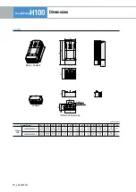
Page 56: ...e 400V LSLV0008H100 2 160 6 30 137 5 39 232 9 13 216 5 8 52 10 5 0 41 181 7 13 5 0 20 5 0 20 3 3 LSLV0015H100 2 160 6 30 137 5 39 232 9 13 216 5 8 52 10 5 0 41 181 7 13 5 0 20 5 0 20 3 3 LSLV0022H100 2 160 6 30 137 5 39 232 9 13 216 5 8 52 10 5 0 41 181 7 13 5 0 20 5 0 20 3 3 LSLV0037H100 2 160 6 30 137 5 39 232 9 13 216 5 8 52 10 5 0 41 181 7 13 5 0 20 5 0 20 3 3 LSLV0055H100 4 160 6 30 137 5 39 ...

Page 57: ...450H100 4 325 12 08 282 11 10 510 20 08 486 5 19 15 16 0 63 284 11 18 7 0 28 7 0 28 35 LSLV0550H100 4 325 12 08 282 11 10 510 20 08 486 5 19 15 16 0 63 284 11 18 7 0 28 7 0 28 35 Unit mm inches Product Model W1 W2 H1 H2 H3 D A B kg 3 Phase 200V LSLV0185H100 2 220 8 66 193 8 7 63 350 13 78 331 13 03 13 0 51 223 2 8 79 6 0 24 6 0 24 7 1 3 Phase 400V LSLV0220H100 4 220 8 66 193 8 7 63 350 13 78 331 1...

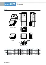
Page 58: ...00H100 4 426 16 77 320 12 60 922 3 36 31 895 5 35 26 15 5 0 61 440 17 32 11 0 43 11 0 43 120 LSLV2500H100 4 426 16 77 320 12 60 922 3 36 31 895 5 35 26 15 5 0 61 440 17 32 11 0 43 11 0 43 120 LSLV3150H100 4 600 23 62 420 16 54 1000 39 37 972 38 27 15 0 59 500 19 69 14 0 55 14 0 55 185 5 LSLV3550H100 4 600 23 62 420 16 54 1000 39 37 972 38 27 15 0 59 500 19 69 14 0 55 14 0 55 185 5 LSLV4000H100 4 6...

Page 59: ...1 181 7 13 55 1 2 17 186 7 32 178 7 01 251 5 9 90 235 9 25 8 4 0 33 3 7 LSLV0110H100 2 206 8 11 264 5 10 41 181 7 13 55 1 2 17 186 7 32 178 7 01 251 5 9 90 235 9 25 8 4 0 33 3 7 3 Phase 400V LSLV0008H100 4 206 8 11 264 5 10 41 181 7 13 55 1 2 17 186 7 32 178 7 01 251 5 9 90 235 9 25 8 4 0 33 3 7 LSLV0015H100 4 206 8 11 264 5 10 41 181 7 13 55 1 2 17 186 7 32 178 7 01 251 5 9 90 235 9 25 8 4 0 33 3...

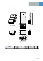
Page 60: ...se 200V LSLV0150H100 2 225 2 8 87 322 7 12 70 205 3 8 08 72 1 2 84 205 2 8 08 197 5 7 78 309 7 12 19 292 5 11 52 9 3 0 34 5 2 3 Phase 400V LSLV0150H100 4 225 2 8 87 322 7 12 70 205 3 8 08 72 1 2 84 205 2 8 08 197 5 7 78 309 7 12 19 292 5 11 52 9 3 0 34 5 2 LSLV0185H100 4 225 2 8 87 322 7 12 70 205 3 8 08 72 1 2 84 205 2 8 08 197 5 7 78 309 7 12 19 292 5 11 52 9 3 0 34 5 4 ...

Page 61: ...se 200V LSLV0185H100 2 267 10 51 384 5 15 14 223 2 8 79 93 6 3 69 247 9 72 239 9 41 371 5 14 63 352 13 86 9 5 0 37 8 3 3 Phase 400V LSLV0220H100 4 267 10 51 384 5 15 14 223 2 8 79 93 6 3 69 247 9 72 239 9 41 371 5 14 63 352 13 86 9 5 0 37 8 3 LSLV0300H100 4 267 10 51 384 5 15 14 223 2 8 79 93 6 3 69 247 9 72 239 9 41 371 5 14 63 352 13 86 9 5 0 37 8 3 ...

Page 62: ...ange Flange W1 A1 W1 B1 B2 A2 W1 H1 H3 H2 W2 D2 D1 W2 4 Ø7 Unit mm inches Product Model W1 W2 H1 H2 H3 D1 D2 A1 A2 B1 B2 kg 3 Phase 400V LSLV0370H100 4 275 10 83 232 9 13 495 19 49 478 5 18 84 7 5 0 30 284 11 18 100 3 94 55 2 17 24 0 98 35 5 1 40 24 0 98 26 4 ...

Page 63: ...roduct Model W1 W2 H1 H2 H3 D1 D2 A1 A2 B1 B2 kg 3 Phase 400V LSLV0450H100 4 325 12 80 282 11 10 555 5 21 87 539 21 22 7 5 0 30 284 11 18 100 3 94 57 5 2 26 24 0 94 35 5 1 40 24 0 94 35 4 LSLV0550H100 4 325 12 80 282 11 10 555 5 21 87 539 21 22 7 5 0 30 284 11 18 100 3 94 57 5 2 26 24 0 94 35 5 1 40 24 0 94 35 4 ...

Page 64: ...m inches Product Model W1 W2 H1 H2 H3 D1 D2 A1 A2 B1 B2 kg 3 Phase 400V LSLV0750H100 4 325 12 80 275 10 83 605 5 23 84 587 23 11 9 5 0 37 309 12 17 130 5 12 68 5 2 69 24 0 94 46 5 1 83 24 0 94 43 5 LSLV0900H100 4 325 12 80 275 10 83 605 5 23 84 587 23 11 9 5 0 37 309 12 17 130 5 12 68 5 2 69 24 0 94 46 5 1 83 24 0 94 43 5 ...

Page 65: ...5 117 6 4 63 78 3 07 43 5 1 71 78 3 07 32 5 1 28 3 9 LSLV0110H100 2 160 6 30 267 8 10 54 232 9 13 55 6 2 19 181 7 13 56 7 2 23 52 5 2 07 44 1 73 21 5 0 85 117 6 4 63 78 3 07 43 5 1 71 78 3 07 32 5 1 28 3 9 3 Phase 400V LSLV0008H100 4 160 6 30 267 8 10 54 232 9 13 55 6 2 19 181 7 13 56 7 2 23 52 5 2 07 44 1 73 21 5 0 85 117 6 4 63 78 3 07 43 5 1 71 78 3 07 32 5 1 28 3 9 LSLV0015H100 4 160 6 30 267 ...

Page 66: ... 08 73 7 2 90 56 5 2 22 44 1 73 24 5 0 96 125 9 4 96 90 3 54 45 7 1 80 90 3 54 33 1 30 180 7 09 55 5 2 19 54 5 2 15 2 5 0 10 5 2 3 Phase 400V LSLV0150H100 4 180 7 09 325 8 12 83 290 11 42 60 2 36 205 3 8 08 73 7 2 90 56 5 2 22 44 1 73 24 5 0 96 125 9 4 96 90 3 54 45 7 1 80 90 3 54 33 1 30 180 7 09 55 5 2 19 54 5 2 15 2 5 0 10 5 2 LSLV0185H100 4 180 7 09 325 8 12 83 290 11 42 60 2 36 205 3 8 08 73 ...

Page 67: ... 350 13 78 64 2 52 223 2 8 79 96 4 3 80 53 2 09 44 1 73 21 0 83 120 4 72 88 3 46 43 1 69 84 3 31 34 1 34 215 8 46 132 5 20 5 2 3 Phase 400V LSLV0220H100 4 220 8 66 382 5 15 06 350 13 78 64 2 52 223 2 8 79 96 4 3 80 53 2 09 44 1 73 21 0 83 120 4 72 88 3 46 43 1 69 84 3 31 34 1 34 215 8 46 132 5 20 5 2 LSLV0300H100 4 220 8 66 382 5 15 06 350 13 78 64 2 52 223 2 8 79 96 4 3 80 53 2 09 44 1 73 21 0 83...

Page 68: ...it 3 Ø44 5 2 Ø22 3 A1 A2 C B3 B2 B4 B1 H3 Withoutrubberpacking Unit mm inches Product Model W H1 H2 H3 D1 D2 A1 A2 B1 B2 B3 B4 C kg 3 Phase 400V LSLV0370H100 4 275 10 83 521 5 20 53 450 17 72 112 5 4 43 284 11 18 100 3 94 162 6 38 81 3 19 184 7 24 160 6 30 105 8 4 17 8 0 31 275 10 83 28 7 ...

Page 69: ...uct Model W H1 H2 H3 D1 D2 A1 A2 B1 B2 B3 B4 C kg 3 Phase 400V LSLV0450H100 4 325 12 80 600 5 23 64 510 20 08 134 5 28 284 11 18 100 3 94 162 6 38 81 3 19 184 7 24 160 6 30 105 8 4 17 8 0 31 325 12 80 38 4 LSLV0550H100 4 325 12 80 600 5 23 64 510 20 08 134 5 28 284 11 18 100 3 94 162 6 38 81 3 19 184 7 24 160 6 30 105 8 4 17 8 0 31 325 12 80 38 4 ...

Page 70: ...nches Product Model W H1 H2 H3 D1 D2 A1 A2 B1 B2 B3 B4 C kg 3 Phase 400V LSLV0750H100 4 325 12 80 685 5 26 99 550 21 65 183 7 20 309 12 17 130 5 12 192 7 56 81 3 19 179 7 05 155 6 10 100 75 3 97 8 0 31 325 12 80 47 2 LSLV0900H100 4 325 12 80 685 5 26 99 550 21 65 183 7 20 309 12 17 130 5 12 192 7 56 81 3 19 179 7 05 155 6 10 100 75 3 97 8 0 31 325 12 80 47 2 ...

Page 71: ...279 5 11 00 386 15 20 173 6 81 369 14 53 180 7 09 90 3 54 196 7 72 172 25 6 78 134 75 5 31 49 75 1 96 62 31 LSLV1320H100 4 300 11 81 958 5 37 74 706 27 80 279 5 11 00 386 15 20 173 6 81 369 14 53 180 7 09 90 3 54 196 7 72 172 25 6 78 134 75 5 31 49 75 1 96 62 31 D1 H1 H2 D2 W D3 H3 A2 A1 B4 B3 B2 D1 6 Ø63 5 2 Ø22 5 Conduit Drive Conduit Withoutrubberpacking ...

Page 72: ...hes Product Model W H1 H2 H3 D1 D2 D3 A1 A2 B1 B2 B3 B4 kg 3 Phase 400V LSLV1600H100 4 380 14 96 985 38 78 705 27 76 308 12 13 396 15 59 168 6 61 381 15 00 220 8 66 106 4 17 213 8 39 186 7 32 148 5 83 58 2 28 81 24 LSLV1850H100 4 380 14 96 985 38 78 705 27 76 308 12 13 396 15 59 168 6 61 381 15 00 220 8 66 106 4 17 213 8 39 186 7 32 148 5 83 58 2 28 81 24 ...

Page 73: ...1 920 36 22 482 18 98 440 17 32 199 7 83 241 9 49 179 7 05 112 4 41 LSLV2500H100 4 426 16 77 1360 3 53 56 922 3 36 31 920 36 22 482 18 98 440 17 32 199 7 83 241 9 49 179 7 05 112 4 41 Product Model B1 B2 B3 B4 C1 C2 C3 C4 C5 C6 kg 3 Phase 400V LSLV2200H100 4 241 9 49 217 8 54 168 6 61 63 2 48 86 3 39 123 4 84 198 7 80 235 9 25 310 12 20 347 13 66 130 54 LSLV2500H100 4 241 9 49 217 8 54 168 6 61 63...

Page 74: ... 10 1002 39 45 1000 39 37 572 5 22 54 580 22 83 253 9 96 327 12 87 210 8 27 40 1 57 235 9 25 105 4 13 190 7 48 380 14 96 205 72 LSLV3550H100 4 600 23 62 1552 61 10 1002 39 45 1000 39 37 572 5 22 54 580 22 83 253 9 96 327 12 87 210 8 27 40 1 57 235 9 25 105 4 13 190 7 48 380 14 96 205 72 LSLV4000H100 4 600 23 62 1552 61 10 1002 39 45 1000 39 37 572 5 22 54 580 22 83 253 9 96 327 12 87 210 8 27 40 1...

Page 75: ...Ø22 5 Withoutrubberpacking Unit mm inches Product Model W H1 H2 H3 H4 D1 D2 D3 A1 A2 A3 B1 B2 B3 C1 C2 kg 3 Phase 400V LSLV5000H100 4 776 30 55 1606 63 23 1059 5 41 71 1054 41 50 592 4 23 32 618 5 24 35 251 5 9 90 367 14 45 190 7 48 247 5 9 74 80 3 15 270 10 63 100 3 94 250 9 84 190 7 48 570 22 44 290 91 ...

Page 76: ...00 0 16 62 0 32 62 18 5 125 0 13 77 0 29 80 3 Phase400V 0 75 10 600 8 09 2 5 16 17 3 1 5 10 5 05 4 10 11 4 2 2 15 3 37 6 6 74 6 3 7 20 2 25 9 5 05 8 5 5 32 1 56 13 3 56 13 7 5 35 1 16 17 2 53 18 11 50 0 76 27 1 64 26 15 63 0 61 33 1 42 33 18 5 70 0 48 43 0 98 42 22 100 0 40 51 0 88 50 30 125 0 29 69 0 59 68 37 0 29 69 BuiltIn 45 160 0 24 85 55 200 0 20 100 75 250 0 15 134 90 350 0 13 160 110 350 0...

Page 77: ...50 45 ABS203c 225 UTE250 225 225 MC 185a 185 55 ABS203c 250 UTE250 250 250 MC 185a 185 75 ABS403c 300 UTE400 300 EBS403c 300 MC 225a 225 90 ABS403c 350 UTE400 350 350 MC 330a 330 3 Phase400V 110 ABS603c 500 UTS600 500 EBS603c 500 MC 400a 400 132 ABS603c 600 600 630 160 ABS603c 630 600 630 MC 630a 630 185 ABS803c 800 UTS800 800 EBS803c 800 220 ABS803c 800 800 800 MC 800a 800 250 ABS1003c 1000 1000 ...

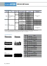
Page 78: ...stor refertothetableof 11 7 6DB Resistors 200V 30 37kW SV370DBU 2U Refertotheappearanceof Group1 45 55kW SV550DBU 2U 75kW SV370DBU 2U 2Set 200V 30 37kW SV370DBU 4U 45 55kW SV550DBU 4U 75kW SV750DBU 4U 90kW SV550DBU 4U 2Set 110 132kW SV750DBU 4U 2Set 160kW SV750DBU 4U 3Set NonULType TypeC ResistanceofDBResistor refertothemanualofDBUnit 200V 30 37kW LSLV0370DBU 2LN RefertotheappearanceofGroup5 LSLV0...

Page 79: ...2400 40 2000 4000 15 45 2000 4000 32 2400 4800 18 5 35 2400 4800 20 3600 7200 22 30 2400 4800 20 3600 7200 30 20 3600 7200 16 5000 10000 37 16 9 3 2 6 4 12 5 10 45 11 4 4 8 9 6 10 6 4 12 8 55 11 4 4 8 9 6 8 4 7 2 14 4 75 8 4 6 4 12 8 6 10 20 90 6 10 20 5 13 26 110 5 13 26 4 16 32 132 4 16 32 3 4 20 40 160 3 4 20 40 2 8 24 48 185 2 8 24 48 2 4 26 52 220 2 4 26 52 2 30 60 250 132kWDBUnitandResistor ...

Page 80: ...r Dynamic Braking Resistor 110 500kW H100 P2 N G R L1 3O Input power S L2 T L3 50 60 Hz B2 B1 U V W B P N B1 B2 P N G R L1 3O Input power S L2 T L3 50 60 Hz B2 B1 Motor DynamicBreaking DB Unit DBResistorBasicWiring BornesdelaDBU Description B1 B2 Wirecorrectlyreferringtowiringdiagram DBResistorsconnectwithB1 B2ofDBUnit DBUnit DBResistor ...

Page 81: ...H100 _ 81 EnergySavingDrive Memo ...

Page 82: ...82_ LS ELECTRIC FanandPumpH100 Memo ...

Page 83: ...H100 _ 83 EnergySavingDrive Memo ...

Page 84: ... 8240 E Mail jschuna lselectric biz LS ELECTRIC America Inc Chicago USA Tel 1 800 891 2941 Fax 1 847 383 6543 E Mail sales us lselectric com Headquarter LS Yongsan Tower 92 Hangang daero Yongsan gu Seoul 04386 Korea Tel 82 2 2034 4620 E Mail drivesales lselectric co kr Overseas Branches LS ELECTRIC Shanghai Office China Tel 86 21 5237 9977 Fax 86 21 5237 7192 E Mail tsjun lselectric com cn LS ELEC...

Reviews: