L7C Series AC Servo Drives Quick Start Guide
Page 15 of 60
L7C Servo Drives Quick Start Guide – 1st Ed. Rev A, 11/29/2021
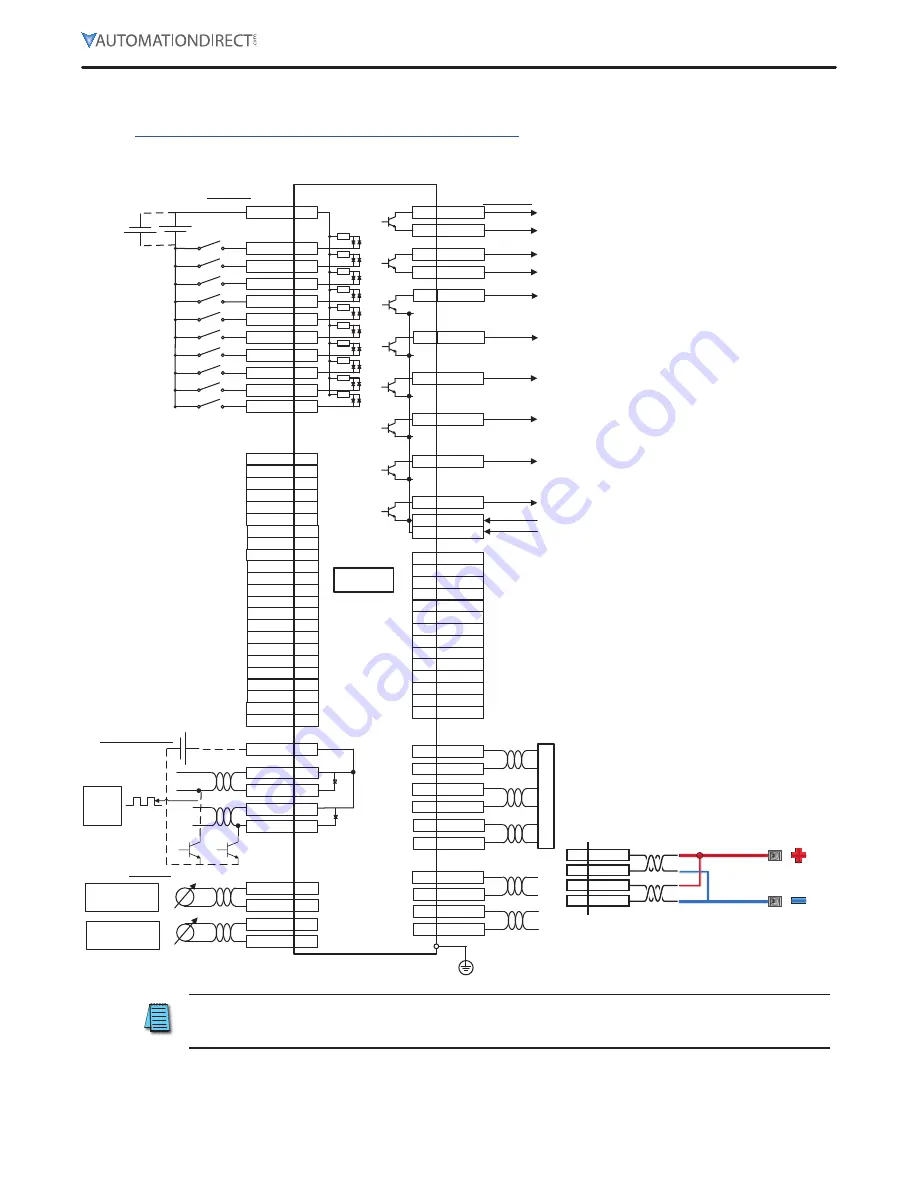
I/O Connection Wiring Diagram with Default Functions
I/O Connection wiring diagram is shown below. For a printable terminal label, go to:
https://www.automationdirect.com/pn/APC-VSCN1T-AD
.
See “Terminal Assignments and Wire Colors” on page 12 for terminal assignments.
SVON
47
SPD1
23
SPD2
22
SPD3
21
A-RST
17
JDIR
46
POT
20
NOT
19
ALARM+
38
ALARM-
39
RDY+
40
RDY-
41
50
+24V IN
Digital input
Digital output
DC 24V
3.92k
Ω
INSPD
**
VLMT
**
(DI1)
(DI2)
(DI3)
(DI4)
(DI5)
(DI6)
(DO1)
(DO2)
WARN
**
ZSPD
43
(DO3)
BRAKE
44
(DO4)
CN1
PF-
10
9
PF+
PR-
12
11
PR+
(DI7)
(DI8)
GAIN2
PCON
PCL
**
**
**
NCL
**
IOUT0
**
INPOS2
**
IOUT1
**
IOUT2
**
RS-422
TXD+
2
RXD+
6
RXD-
7
EMG
18
STOP
48
ISEL0
**
ISEL1
**
ISEL2
**
ISEL3
**
ISEL4
**
Command pulse input
INPOS1
45
ORG
**
(DO5)
ALO0
16
EOS
**
note)
(DO6)
ALO1
15
TGON
**
ALO2
14
TLMT
**
ISEL5
**
H-START
**
INHIBIT
MODE
**
**
PAUSE
**
ABS_RQ
**
JSTART
**
JDIR
**
IOUT3
**
IOUT4
**
IOUT5
**
(DI9)
(DIA)
AGND
8
1
TRQCOM
AGND
8
27
SPDCOM
Analog input
-10V~+10V
Encoder output
AO
32
/AO
33
BO
30
/BO
31
ZO
4
/ZO
5
U
p
p
e
r le
ve
l c
o
n
tro
ller
49
PULCOM
Line drive
Open collector
Upper
level
controller
Analog torque input
(Command/limit)
Analog velocity input
(Command/override)
TXD-
3
-10V~+10V
PCLR
**
AOVR
**
LVSF1
LVSF2
**
**
GND24
25
GND24
24
EGEAR1
**
EGEAR2
**
note)
(DO7)
note)
(DO8)
2
TXD+
3
TXD–
6
RXD+
7
RXD–
NOTE:
When connecting a single RS422 servo
to an RS485 PLC, use the following wiring:
PLC RS485 terminals
For best performance (and when communicating with multiple servos),
use an RS485 to RS422 adapter with the PLC
For the most reliable PLC/drive communication, limit the drive baud
rate (0x3002) to a maximum of 19,200 baud.
NOTE: Input signals DI1–DI10 and output signals DO1–DO8 are factory default signals and can
be reconfigured. Note that DO6-DO8 are permanently fixed as status output signals, but all
other digital I/O can be reprogrammed.


