L7C Series AC Servo Drives Quick Start Guide
Page 17 of 60
L7C Servo Drives Quick Start Guide – 1st Ed. Rev A, 11/29/2021
I/O Wiring and Option Details
Analog
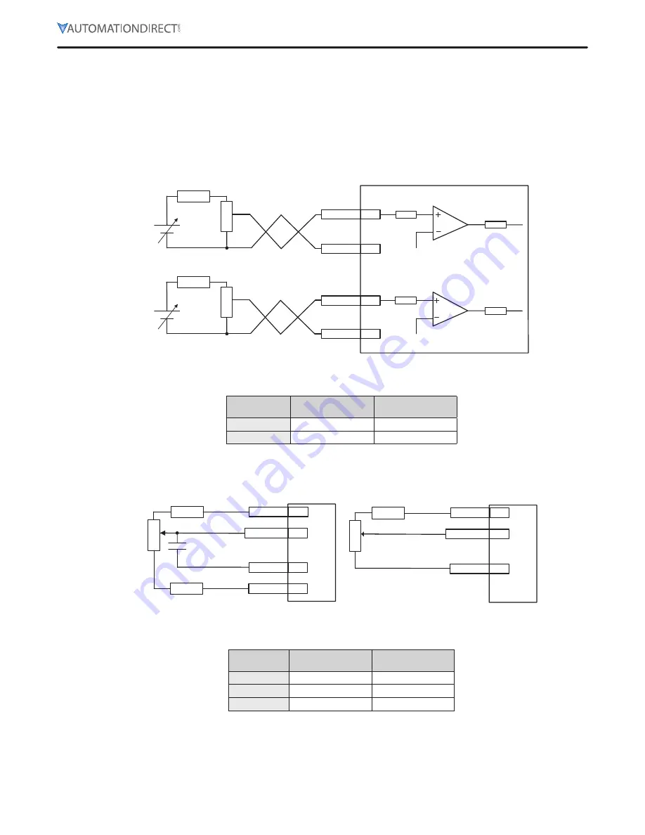
1) For information on how to operate analog input signals, refer to the User Manual, section 4.5
“Analog Velocity Override,” section 6.2 “Analog Velocity Command,” section 7.2 “Analog Torque
Command Scale,” and section 10.8 “Torque Limit Function.”
2) The range of analog input signals is -10V to 10V.
3) The impedance for input signals is approximately 10K
Ω
.
Servo drive
DC±24V
AGND
8
1
AGND
8
27
SPDCOM
R2
R1
TRQCOM
R2
R1
DC±24V
4) Example of resistance selection for use of 24V for input voltage:
No.
R1
R2
1
5K
Ω
6K
Ω
2
10K
Ω
12K
Ω
5) Examples of using in12V and -12V power sources:
AGND
8
1, 27
R2
R1
Analog Input
34
+12[V]
-12[V]
35
R2
0.1[uF]
AGND
8
1, 27
R2
R1
34
+12[V]
Analog Input
6) Example of resistance selection for use of 12V for input voltage:
No.
R1
R2
1
10K
Ω
660
Ω
2
5K
Ω
330
Ω
3
2K
Ω
132
Ω
7) Example R1 potentiometers:
•
GSDA-5K: 5K potentiometer with 0-100% dial
•
ECX2300-5K: 5k potentiometer
•
ECX2300-10K: 10k potentiometer


