L7C Series AC Servo Drives Quick Start Guide
Page 39 of 60
L7C Servo Drives Quick Start Guide – 1st Ed. Rev A, 11/29/2021
Step 3: Control Mode Selection
Puls
e Mode S
tep 3
Substep
Task
A
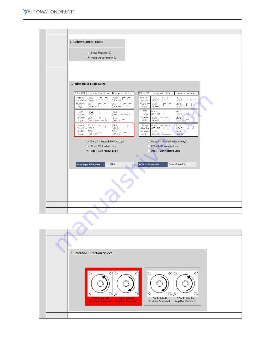
On the
Select Control Mode
screen, select
Pulse Input Position (1)
for Control Mode (Object 0x3000)
Click
Next
B
On the
Pulse Input Logic Select
screen, select the type of pulse train you want to use from the host
controller or PLC
Pulse + Sign Positive Logic
is selected in the image below This is the typical setting
for PLC high speed pulse outputs
For the L7C drive CN1 connector, the pulse inputs terminate as follows:
• Pulse (or CW) signal will terminate to pin 9 PF+ (A5) and pin 10 PF- (B5)
• Sign (or CCW) signal will terminate to pin 11 PR+ (A6) and pin 12 PR- (B6)
See section 256 of the User Manual for more details (and how to connect Open Collector high speed
pulses)
Note:
The pin numbers in the image in the software are for a different LS Electric drive Be sure to use
pins 9, 10, 11, and 12
C
For Pulse Input Filter Select and PCLEAR Mode Select, use the default settings for initial setup/testing
D
Click
Next
Step 4: Set Rotation Direction
Puls
e Mode S
tep 4
Substep
Task
A
Set rotation direction on the
Rotation Direction Select
screen This sets which motor direction is
considered positive or negative If this isn’t known, it can be set later in 0x2004 (in the Object Dictionary
\ Basic tab)
B
Click
Next


