background image

User Manual

GIPAM

GIMAC-II

GMPC-III

User Manual  2003 / (01)  2003.10 Printed in Korea STAFF

  LG  Industrial  Trading  (Shanghai) Co.,  Ltd      China

Address: Room1705-1707, 17th Floor Xinda 
                Commerical Building No 318, Xian Xia Road Shanahai
Tel: 86-21-6252-4291                                   Fax: 86-21-6278-4372
e-mail: hgseo@lgis.com
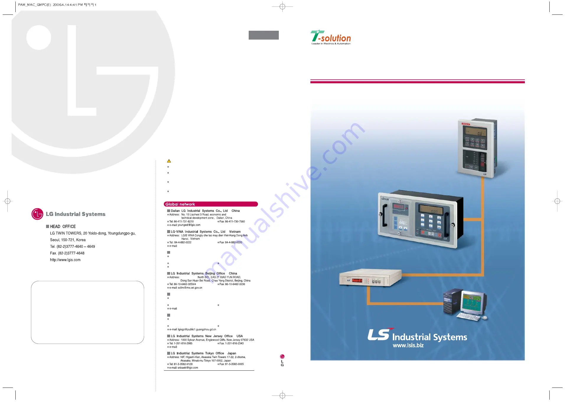
   Safety Instructions

For your safety, please read user’s manual thoroughly before operating.

Contact the nearest authorized service facility for examination, repair,
 or adjustment.

Please contact qualified service technician when you need maintenance.
Do not disassemble or repair by yourself!

Any maintenance and inspection shall be performed by the personnel having 
expertise concerned.

  LG  Industrial  Systems  Shanghai  Office     China

Address: Room1705-1707, 17th Floor Xinda Commerical Building
                No 318, Xian Xia Road Shanahai, China
Tel: 86-21-6278-4370                                   Fax: 86-21-6278-4301

  LG  Industrial  Systems  Guangzhou  Office      China

Address: Room 303, 3F, Zheng Sheng Building, No  5-6, Tian He 
                Bei Road, Guangzhou, China
Tel: 86-20-8755-3410                                   Fax: 86-20-8755-3408

srjo@hn.vnn.vn

Room 303, 3F

sdhwang@lgis.com

younsupl@lgisusa.com

2003-10

Specifications in this catalog are subject to change without notice due to 
continuous product development and improvement.

User Manual 

(GIPAM

GIMAC-II

GMPC-III

)

Summary of Contents for GIMAC-II

Page 1: ...tenance Do not disassemble or repair by yourself Any maintenance and inspection shall be performed by the personnel having expertise concerned LG Industrial Systems Shanghai Office China Address Room1...

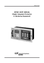
Page 2: ...GIPAM USER MANUAL Digital Integrated Protection Monitoring Equipment GIPAM User Manual...

Page 3: ...stallation Method 23 7 2 Setting method of DIP Switch 23 7 3 Setting communication address number 25 7 4 Affirmation of setting 25 7 5 Connection of input circuit 25 7 6 External connection drawing 27...

Page 4: ...on relays operating and transffering switchs and lamps in one unit Various types of characteristic curves are provided It makes high reliance of protection by adopting technology of digitail filter ap...

Page 5: ...ver voltage relay OVGR Over voltage ground relay SGR Sensitive ground relay 3 Indication Function Indicates the status of protection relay and circuit breaker on front LED Displaying status via digita...

Page 6: ...5 GIPAM User Manual 4 External view and System structure 4 1 External view and part name 4 2 System structure...

Page 7: ...k up Active Watt Average Value LCD 0 9999 MW Bargraph 0 to 120 2 0 Power Reactive Vars Average Value LCD 0 9999 MVars Bargraph 0 to 120 2 0 Active Wh Accumulated Value 0 999999 MWh 2 0 Energy Reactive...

Page 8: ...s communicated with host When operator select special function mode LED lamp will be turned on 5 Setting a metering part Setting object Detail Location Metamorphosis Ratio CT Ratio DIP Switch 1 5bit P...

Page 9: ...lse voltage Between electrical circuit ground AC 2 000V 1min Between electrical circuit phase AC 2 000V 1min Power Frequency withstand Voltage Between electrical circuit terminal AC 1 000V 1min 5kV fo...

Page 10: ...played by pushing the measurement selection key Easurement key displays 1 Current Display panel shows current value of phase R at the initial status Each phase of current measurement value will be dis...

Page 11: ...switch Varh 5 Power Factor Power factor is displayed by pushing touch switch PF with unit and also displayed LEAD or LAG 6 Frequency Frequency is displayed by pushing touch switch F with Hz unit and i...

Page 12: ...If press this button local output contact will be on and it makes possible to operate C B on or off by pressing the keys on the front 2 Remote It is the key for the remote control If press this butto...

Page 13: ...of adjustment please refer to appendix 6 2 2 Operation 1 Display of operating status After power is on DOT matrix and LCD part will be turned on during 1 second If displayed Run it means normal opera...

Page 14: ...e time delay curves respectively 3 XX AL TP Operation mode setting XX no operation AL alarm mode TP alarm trip mode 3 Display of fault status Fault LED is turned on in case of error detected each fact...

Page 15: ...surement calculated by formula as table Ir Is It I Ov Uv V Io Run 5 Display of System error Error code is blinking and displaying when internal trouble occurs Error codes are same as followings ERR 1...

Page 16: ...15 GIPAM User Manual...

Page 17: ...16 GIPAM User Manual...

Page 18: ...17 GIPAM User Manual...

Page 19: ...18 GIPAM User Manual...

Page 20: ...19 GIPAM User Manual...

Page 21: ...20 GIPAM User Manual...

Page 22: ...wing formulas Time Delay Characteristic IEC 255 3 is applied Standard Inverse SI T Definite Time D2 T 2 Definite Time D4 T 4 Definite Time D8 T 8 Very Inverse VI T Vid I Operated Current Is Set Curren...

Page 23: ...0 1 038 15 00 2 516 15 00 0 964 16 00 2 455 16 00 0 900 17 00 2 401 17 00 0 844 18 00 2 353 18 00 0 794 19 00 2 308 19 00 0 750 20 00 2 267 20 00 0 711 Extreme Inverse Time Long Inverse Time I Is sec...

Page 24: ...23 GIPAM User Manual 6 2 4 Characteristic Operation Curve 1 SI Standard Inverse Time OCR OCGR OVGR t TL TL 0 05 1 00 0 14 I Is 0 02 1...

Page 25: ...24 GIPAM User Manual 2 VI Very Inverse Time OCR OCGR t TL TL 0 05 1 00 13 5 I Is 1...

Page 26: ...25 GIPAM User Manual 3 EI Extremely Inverse Time OCR OCGR t TL TL 0 05 1 00 80 I Is 2 1...

Page 27: ...26 GIPAM User Manual 4 LI Long Inverse Time OCR OCGR t TL TL 0 05 1 00 120 I Is 1...

Page 28: ...27 GIPAM User Manual 5 SGR Current and voltage in Zone 1 Vo Vos Io Ios RCA Relay Characteristic Angle...

Page 29: ...t an Address Number with the Address Knob which is deeply inside of the Main Board 3 Supply the power DC 110V 4 Input the Voltage and Current 5 By pressing the CLEAR S W on the front reset CB Operatio...

Page 30: ...1 600 5A 0 1 1 0 0 750 5A 0 1 0 1 1 800 5A 0 1 0 1 0 1000 5A 0 1 0 0 1 1200 5A 0 1 0 0 0 1500 5A 0 0 1 1 1 2000 5A 0 0 1 1 0 2500 5A 0 0 1 0 1 3000 5A 0 0 1 0 0 4000 5A 0 0 0 1 1 5000 5A 0 0 0 1 0 600...

Page 31: ...ion data with using FUNC Key among the Measurement Keys on the front When the LED of FUNC Key is on you can easily check out the data by pressing V A F or W Key 1 PT Ratio Pressing V key when the LED...

Page 32: ...31 GIPAM User Manual 2 Sigle Phase Three Wire System 3 Three Phase Three Wire System with 2 CTs...

Page 33: ...32 GIPAM User Manual 4 Three Phase Three Wire System with 3 CTs with 3PTs...

Page 34: ...33 GIPAM User Manual 5 Three Phase Four Wire Syste note 1 6 Connecting with ZCT 7 Connecting with GPT...

Page 35: ...xternal connection 1 Avoid parallel connection with other devices that generate noises 2 Press the CLEAR Switch to initialize all data after installing device It must be supplied the well smooting DC...

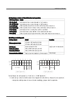
Page 36: ...35 GIPAM User Manual 3 Terminal Block 7 7 External Dimension mm...

Page 37: ...n Speed 250kbps 2 Cable Lenth max 1000m 3 Insulation Pulse Transformer 4 Connection 4 wire Multi drop 5 Signal Modulation Bipolar 6 Communication Address 0 255 with Hexa Decimal Switch 7 Communication...

Page 38: ...sier to troubleshoot 1 Event Recording when the relays in GIPAM has been operated OCR OCGR OVR UVR SGR OVGR when the CB has been controlled when the status of the CB has been changed 2 Synchronization...

Page 39: ...the main board or working voltage 3 If one of the Error Code is displayed on the LCD in Protection part as below ERR 1 ERR 2 ERR 3 Errors of Input circuit or the power in Analog circuit Errors of the...

Page 40: ...out the device 4 For installing the device after replacement take the step three to one 5 Set CT ratio PT ratio and wirings with DIP Switches 6 Supply the control power DC 110V and check out the below...

Page 41: ...66 0 532 0 798 1 064 1 330 1 596 1 862 2 128 2 394 2 660 1400 0 258 0 517 0 775 1 033 1 292 1 550 1 808 2 066 2 325 2 583 1500 0 252 0 503 0 755 1 006 1 258 1 509 1 761 2 012 2 264 2 516 1600 0 246 0...

Page 42: ...2 000 3 000 4 000 5 000 6 000 7 000 8 000 9 000 10 000 400 0 533 1 067 1 600 2 133 2 667 3 200 3 733 4 267 4 800 5 333 500 0 333 0 667 1 000 1 333 1 667 2 000 2 333 2 667 3 000 3 333 600 0 229 0 457...

Page 43: ...9 17 143 900 1 500 3 000 4 500 6 000 7 500 9 000 10 500 12 000 13 500 15 000 1000 1 333 2 667 4 000 5 333 6 667 8 000 9 333 10 667 12 000 13 333 1100 1 200 2 400 3 600 4 800 6 000 7 200 8 400 9 600 10...

Page 44: ...GIMAC II USER MANUAL Digital Integrated Metering Control Equipment GIMAC II User Manual...

Page 45: ...stem diagram 3 2 1 Features 3 2 2 System Diagram 4 3 Specification 4 3 1 Metering 4 4 Operational functions 6 4 1 Display 6 4 2 Special function switch 7 4 3 Etc 7 5 Installation and operation 8 5 1 S...

Page 46: ...body 3 Easy to modify the specification If there is modifications in the main circuit specifications the GIMAC II correspond it by resetting the phase and line types in the electrical system by use of...

Page 47: ...0 2 6000 A Current Bar graph 0 120 4 LCD 0 9999 MW Watt Bar graph 0 120 4 LCD 0 9999 Mvar Var Bar graph 0 120 Watt hour 0 999999 MWh Var hour 6 LCD 0 999999 MVarh Power factor 3 LCD Lead Lag 0 100 Fr...

Page 48: ...n Barrery on Back up DIP switch 1 DIP switch 2 4 Specifications Votage input Less than 0 1VA Burden Current input Less than 1VA Voltage DC110V 10 15 Control power Power Less than 10W Data Back up Min...

Page 49: ...rn Vsn Vtn Vrs Vst Vtr sequence at each time you press the touch switch button 2 Current 1phase 2wires displays the data by Ampere unit 1phase 3wires Displays the voltage by Ir In It sequence at each...

Page 50: ...which is connected to the CB ON input contact When the time is over 9999 hours it display the time by the bargraph on the 10000 hours unit 6 VARH switch Display all the measured data by the following...

Page 51: ...the rear part of the equipment Mis operation display mode Wiring connection type Communication address optional 2 Apply the control power 3 Turn on the DIP Switch 2 Bitl Battery Back up use and press...

Page 52: ...0 1 1 0 13200 110V 0 1 1 1 50 5A 0 0 1 1 1 13800 110V 1 0 0 0 60 5A 0 1 0 0 0 22000 110V 1 0 0 1 75 5A 0 1 0 0 1 22900 110V 1 0 1 0 80 5A 0 1 0 1 0 33000 110V 1 0 1 1 100 5A 0 1 0 1 1 66000 110V 1 1 0...

Page 53: ...10 A57 IgYf AUbiU 5 2 Wiring...

Page 54: ...11 A57 IgYf AUbiU 1 3P4W 3 CT 2 3P3W 3CT With 3PTs...

Page 55: ...12 A57 IgYf AUbiU 3 3P3W 2CT 4 1P3W...

Page 56: ...13 A57 IgYf AUbiU 5 1P2W 6 Odering Information...

Page 57: ...GMPC III USER MANUAL Protocol converter III GMPC III User Manual...

Page 58: ...ols 19 9 1 Introduction 19 9 2 Basic structure of data frame for transmission 19 9 3 Transmitting Junction PROTOCOL 20 9 4 Synchronization PROTOCOL 20 9 5 Internal Setting PROTOCOL 24 10 GIMAC II Prot...

Page 59: ...3 AD7 IgYf AUbiU 1 Components LG LG GMPC III Main Body 1EA I NET CABLE 1EA RS232C CABLE 1EA POWER CALBE 1EA 485 Connector T M Connector...

Page 60: ...etting menu SYNC LED Being on and off while a synchronizing data is transmitting Time Master LED Turned on when Time Master is selected in the setting menu TxD LED Turned on while a data is transmitti...

Page 61: ...port Error LED Turned on when any error is on the internal system MENU Key Changing the setting menu SELECT Key Changing the setting value ENTER key Storing the changed value 2 3 Rear View Power Conn...

Page 62: ...onverting not only a data from remote control system to I Net data but also converting I Net one to the one used remote system In particular GMPC provides MODBUS protocol of MODICON which is widely ac...

Page 63: ...figuration has to be applied between the GMPC For synchronization GMPC is capable to be connected up tp16ea maximum and one of them has to be selected as Time Master RS 232C Multi serial communication...

Page 64: ...eceives information about time from the remote control system and set the timer built in for the time data received For synchronization it is capable to use 1 s or 1 ms unit one For more detailed info...

Page 65: ...tion Speed 2400 57600 bps Condition of the TIME MASTER T M LED Synchronizing between the GMPCs SYNC LED Self Diagnostic ERR LED Communication Status TXD RXD LED Communication Status I Net RUN IDLE LED...

Page 66: ...ing a PROTOCOL MODBUS GMPC I NET RS232 RS485 RS232 RS485 Setting the PARITY BIT No Odd Even 2400 4800 9600 14400 19200 28800 33600 38400 56000 Communication Speed of RS232 485 standards 8 Data Bits No...

Page 67: ...vides synchronizing with the GMPC by means of Time SYNC Protocol which is defined separately If one of the GMPC is selected as a Time Master computer system provides time data for GMPC and the GMPC ma...

Page 68: ...s inside of the Fuse Holder on the rear of the Unit Type should be checked if it is 220V and 2A It has to be checked that the power switch is turned on 8 1 2 The connection of a communications line GM...

Page 69: ...TX 0 TX 1 RX 0 RX 1 RX 0 RX 1 TX 0 TX 1 RX 0 RX 1 TX 0 TX 1 GMPC III GIMAC GIPAM DPR RTU 1 GIMAC GIPAM DPR RTU n 8 1 4 The connection of auxiliary connectors GMPC has a function called S O E Sequence...

Page 70: ...to the next menu press the MENU key 8 2 3 HOUR MINUTE SECOND DISPLAY The Front window displays the present hour minute second Pressing the SEL key once it is changed from Display Mode to Setting Mode...

Page 71: ...ASTER DISPLAY The front window displays whether it is selected as Time Master or not Pressing the SEL key once it is changed from Display Mode to Setting Mode and the value on the display window goes...

Page 72: ...he MENU key while changing the values on the setting menu all the values that has been changed are canceled and it is changed into Display Mode To move to the next menu on Display Mode press the MENU...

Page 73: ...the window one by one To store the one selected among them press the ENT key If you press the MENU key while changing the values on the setting menu all the values that has been changed are canceled a...

Page 74: ...18 AD7 IgYf AUbiU 8 3 MENU TREE 9 Time Date Time Master Sync I NET Address RS 232 RS 485 Parity Bit Baud rate Protocol...

Page 75: ...y 9 2 Basic structure of data frame for transmission Data that flows between GMPC and the Host system is transmitted frame by frame and the basic structure of a frame is as follow P1 P2 DEST E FN LEN...

Page 76: ...as received is discarded when there is ECC error on it The data frame that GMPC has received is also discarded when there is an error in value on it The structure of the data frame Ex 0xFF 0x00 0x23 0...

Page 77: ...0x 0x27 0x00 year mon day hour min sec ECC DATA 0 DATA 1 DATA 2 DATA 3 DATA 4 DATA 5 DATA 6 0x00 year mon day hour min sec START_ROUGH_SYNC Inputting the last two digits of year as binary Inputting th...

Page 78: ...e and the first bit is started transmitting B2 at this point The Host system stores the point that the first frame and the first bit of REQUEST_ADJUST frame is received A2 The Host system transmits TI...

Page 79: ...ART_PRECI_SYNC PC GMPC III 0xFF 0x00 0x 0x21 0x01 ECC DATA 0 0x01 START_PRECI_SYNC REQUEST_ADJUST PC GMPC III 0xFF 0x00 0x 0x21 0x01 ECC DATA 0 0x01 REQUEST_ADJUST TIME_ADJUST PC GMPC III 0xFF 0x00 0x...

Page 80: ...PC has received is discarded when there is ECC error on it The data frame that GMPC has received is recognized as abnormal response E bit 1 when there is an error in value on it The internal setting P...

Page 81: ...our that GMPC displays at present The value of minute that GMPC displays at present The value of second that GMPC displays at present Error check on GMPC 0 No Error 1 Error 0 Non Time Master 1 Time Ma...

Page 82: ...0X00 0X01 WRITE_SYNC_ENABLE OFF ON PC GMPC III 0xFF 0x00 0x 0X42 0x03 ON OFF ECC DATA 0 DATA 1 0x03 0x00 0x01 WRITE_SYNC_ENABLE OFF ON 9 5 4 WRITE_INET_ADDRESS PC GMPC III 0xFF 0x00 0x 0X42 0x04 inet...

Page 83: ...sting STATUS Data b 2nd byte 81h DEVICE ID signifying GIMAC II with SBO function c 3rd byte FF Status of fault input at present Latch Signal MSB 1 1 1 1 1 1 1 1 LSB BIT7 Heavy Fault Output BIT6 Light...

Page 84: ...hase Current Ir S Phase Current Is T Phase Current It 02H Line Voltage between R and S Phase Vrs Line Voltage between S and T Phase Vst Line Voltage between T and R Phase Vtr 03H Power Watt Volt Amper...

Page 85: ...SUM COMMAND SUBCOMMAND 0x100 SUB COMMAND Description 42h WH VARH RESET 43h FAULT RESET 44h RESET the Number of times of CB operation 45h RESET accumulated time when CB is on 10 4 Control Command II 10...

Page 86: ...ol CODE2 0x100 Control CODE1 Control CODE2 Description 9fh 69h Operating CB ON 9eh 96h Operating CB OFF 10 5 ACK NAK Response for Control Command I II 10 5 1 ACK It responds when the Control Command I...

Page 87: ...r Is It In Ir Is It In Operating Status of Relays OVR UVR VG SGR VG 1 1 Sys CB Status ON out OFF out Local On in OFF in Status of Reset Clear SOE R y Set L Rst R Rst Local Clear Command Code Error Cod...

Page 88: ...NT Requesting Current Information Command 11h Sub Command Current Data Command 01h MSB Byte 3 Byte 2 Byte 1 R Phase Current LSB Byte 0 MSB Byte 3 Byte 2 Byte 1 S Phase Current LSB Byte 0 MSB Byte 3 By...

Page 89: ...R phase 1P3W Between T and N Phase LSB Byte 0 Data Check Sum Check Sum The representation follows IEEE Standards 4 Byte Floating Point Number 1P2W 2nd data S T 3rd data T R become null Checksum 1Byte...

Page 90: ...not to include OVERFLOW 11 1 5 Frequency Watt Hour Representing Frequency Watt hour Information Command 14h Sub Command Frequency Watt hour Data Command 04h MSB Byte 3 Byte 2 Byte 1 Frequency LSB Byte...

Page 91: ...3 Byte 2 Byte 1 T Phase Voltage T N LSB Byte 0 Data Check Sum Check Sum The representation follows IEEE Standards 4 Byte Floating Point Number This is available only if 3P4W is set Checksum 1Byte Comm...

Page 92: ...lated to SOE function or responds NAK Message Requesting SOE Data Command 19h Sub Command 0 0 0 0 0 0 Clear Req Req Bit Requesting Data Frame 1 Clear Bit Canceling one frame of the data in Buffer at p...

Page 93: ...It is the value of 4 Byte Long Integer and represents time that present status has been changed as 32bit Binary Number 0hou 0min 0 000sec The MSB Bit 31 of Fault occurred time is Time Valid Flag 1 Nu...

Page 94: ...status Data clear Command 09h Sub Command EOD 03h Device ID 83h T Valid T30 T29 T28 T27 T26 T25 T24 T23 T22 T21 T20 T19 T18 T17 T16 T15 T14 T13 T12 T11 T10 T9 T8 Fault occurred Time T7 T6 T5 T4 T3 T2...

Page 95: ...Data of Measuring Part Command 1Dh Sub Command 00h b Requesting the Set Data for OCR OCGR Command 1Dh Sub Command 01h c Requesting the Set Data for OVR UVR Command 1Dh Sub Command 02h d Requesting th...

Page 96: ...ual Checksum is the sum of each bytes not to include OVERFLOW b OCR OCGR Setting Data Command 0Dh Sub Command 01h Current value of Time Delay char for OCR X X Current value of Instantaneous char for O...

Page 97: ...the Relay operation OCGR Data Selecting the Relay Operation 00 Disable 01 Alarm Only 02 Alarm Trip c OVR UVR Setting Data Command 0Dh SubCommand 02h 0X Up to a decimal point Operating Voltage for OVR...

Page 98: ...ge value of Instantaneous char for OVGR XX 0X Up to a decimal point Operating Time for OVGR XX Down to a decimal point Selecting OVGR Function 0X Operating Current for SGR X X Operating Voltage for SG...

Page 99: ...e residual Checksum is the sum of each bytes not to include OVERFLOW Event Enable It decides to make SOE Data about the event occurred SOE data is made when there is an event occurring which is set 1...

Page 100: ...d 1Byte Data 0 9Byte 256 The residual Checksum is the sum of each bytes not to include OVERFLOW Reply Bit 3 It shows whether ACK response is requested by Control Command 1 Requesting ACK response 0 No...

Page 101: ...nt Not requiring ACK Signal Requiring ACK Signal Command 20h 28h Sub Command Control Point Data Check Sum Check Sum Checksum 1Byte Command 1Byte Sub Command 1Byte Data 0 9Byte 256 The residual Checksu...

Page 102: ...int and for operating control point sequentially 11 3 1 SBO Select Before Operate It applies to command for CB Open Close Transmitting the command for selecting control point to GIPAM GIPAM replies wi...

Page 103: ...e Command 1Byte Sub Command 1Byte Data 0 9Byte 256 The residual Checksum is the sum of each bytes not to include OVERFLOW 11 3 3 2 Control Command Bit 7 Bit 6 Bit 5 Bit 4 Bit 3 Bit 2 Bit 1 Bit 0 Comma...

Page 104: ...ta is displayed in 10ms and the length is 16 bits Default value of Time out is 5 seconds It has to be set over than 1 second 11 3 4 2 Reading Time out data Added to the Data for setting GIPAM Requirin...

Page 105: ...UNSIGNED REGISTER 0 65535 Example 3001 S SIGNED REGISTER 32 768 32767 12 2 2 LONG INTEGER It consists of two registers and is type of 32BIT SIGNED INTEGER Its name is REGISTER_NAME L Example 30001 L...

Page 106: ...05 40001 43341 u RTU Unused Unused 31001 31024 41001 41101 u RTU II Unused Unused 31501 31545 41501 41641 GIMAX III 2001 2141 Unused 32001 32246 42001 42025 GIPAM 3041 3381 Unused 33001 33321 43001 43...

Page 107: ...t Current Status 04h CB RESET Status Data INT 30003 BIT Operation Example 30003 8 0 1 2 Bit7 6 5 Reserved 3 Bit4 CB ON Output Status 4 Bit3 CB OFF Output Status 5 Bit2 0 LOCAL 1 REMOTE 6 Bit1 CB ON In...

Page 108: ...iving ACK response Send CB ON Operate Command 01 06 00 14 9F 69 60 10 Example To send CB OFF SBO command to GIMAC II with station address number 1 1st Step Send CB OFF Select Command 01 06 00 00 61 69...

Page 109: ...t 4 R Rst 3 Local 2 1 0 Clear Command Code 000 wh clear 001 varh clear 010 SOE buffer clear 011 CB ON counter clear 100 CB ON time clear 101 Vo max clear 110 all clear 111 xxx clear nothing GIPAM Inte...

Page 110: ...FLOAT 33085 Example 33085 F 04H Phase Voltage R Phase Voltage FLOAT 33101 Example 33101 F S Phase Voltage FLOAT 33103 Example 33103 F T Phase Voltage FLOAT 33105 Example 33105 F 04h Zero Sequence Vol...

Page 111: ...le 33143 L RELAY SETTING INT 33145 BIT Operation Lower 1 BYTE 7 6 5 4 1 3 remote Setting 2 Local Setting 1 remote fault reset 0 local fault reset Reserved INT 33146 Reserved SUB COMMAND 3 04h SOE DATA...

Page 112: ...wh 05h SOE DATA Remove 3401 Control Command Command for requesting the next data after removing the present data in SOE buffer with single query is not supported 04h Measurement Part SETTING DATA Quer...

Page 113: ...CODE 33224 L X X Lower 1 BYTE OCGR CURVE BCD CODE 33225 0X Lower 1BYTE Operating Time of OCGR BCD CODE 33226 0X XX Higher BYTE 0X Lower BYTE XX Selecting OCGR Function BCD CODE 33227 0X Lower 1BYTE 04...

Page 114: ...1 BYTE SGR Operating Time BCD CODE 33265 XX X0 Higher BYTE 0X Lower BYTE XX Selecting SGR Function BCD CODE 33266 0X Lower 1 BYTE RESERVED BCD CODE 33267 0X Higher 1 BYTE 04h SOE ENABLE and TIMER Sta...

Page 115: ...ith ACK 05h CLEAR WH 3261 Control Command With ACK 05h CLEAR VARH 3281 Control Command With ACK 05h CLEAR ALL SOE DATA 3301 Control Command With ACK 05h CLEAR CB ON COUNT 3321 Control Command With ACK...

Page 116: ...h station address number 1 With ACK QUERY 01 06 0B CC 07 D0 48 7D 06h SBO ARM TIMER SETTING 43001 No ACK Example To send SBO ARM TIMER setting command to SOE GIPAM with station address number 1 No ACK...

Page 117: ...804 L 0 no t m 1 t m Sync_en 39805 H GIMAC SYNC 0 Sync Disable 1 Sync Enable is_sync 39805 L Between GMPC III s 0 Sync Disable 1 Sync Enable Inet_addr 39806 H I NET Address RS232 485 39806 L 0 RS485 1...

Page 118: ...ng of Modbus I O Server 13 1 1 Main View of Modbus I O Server 13 1 2 Com Port Setting Setting COM port to connect with GMPC III MODBUS Select COM port to connecting with GMPC III MODBUS Setting the Ti...

Page 119: ...eating New Topic and Modification of setting variables in created Topic Creating new Topic Modification of setting variables in created Topic Setting the name of Topic The name must be the same name o...

Page 120: ...l Registers in a command to 8 Register Read Set maximum number of Registers in a query to 8 Register Write Set maximum number of Registers in a command to 8 Set time Period between queries 13 1 4 Serv...

Page 121: ...Manual 13 2 1 Definition of Tag Definition of Tag Define new Tag Select old Tag Type the name of the Tag Select type of the Tag Type the comments of the Tag Type initial value of the Tag Type Access...

Page 122: ...with Tag Name starting with I O is external tag Discrete Binary Type 1bit Integer Integer Type 32bit Real Floating Point Type 32bit Message String Type 131Byte in max 13 2 3 Setting Access Name Type...

Page 123: ...sassemble or repair by yourself Any maintenance and inspection shall be performed by the personnel having expertise concerned LG Industrial Systems Shanghai Office China Address Room1705 1707 17th Flo...

Reviews: