


Chapter 7. Usage of Various Functions
7-9
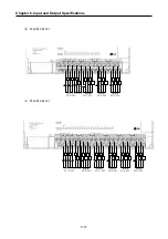
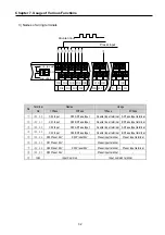
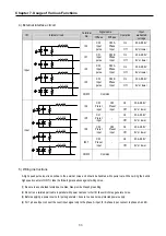
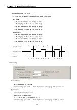
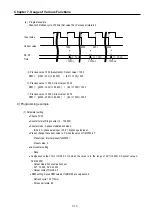
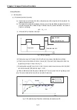
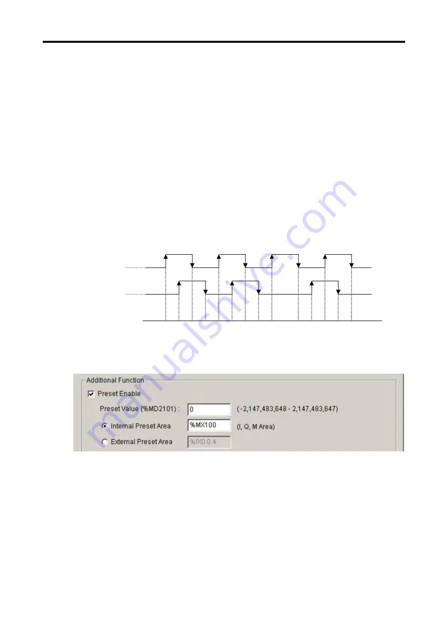
(d) 2-phase multiplication mode (MUL4)
- Up or Down is set automatically by the phase difference between A and B phase.
•
Up counter
- At the rising edge of A-Phase pulse when B-phase is ‘low’.
- At the falling edge of A-Phase pulse when B-phase is ‘high’.
- At the rising edge of B-Phase pulse when A-phase is ‘high’.
- At the falling edge of B-Phase pulse when A-phase is ‘low’.
•
Down counter
- At the rising edge of A-Phase pulse when B-phase is ‘high’.
- At the falling edge of A-Phase pulse when B-phase is ‘low’.
- At the rising edge of B-Phase pulse when A-phase is ‘low’.
- At the falling edge of B-Phase pulse when A-phase is ‘high’.
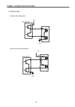
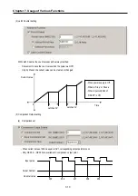
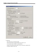
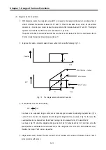
(3) Preset setting
(a) Internal Preset
- Set internal preset area and preset value.
- Current value of high speed counter is replaced with preset value at the rising edge of internal preset device.
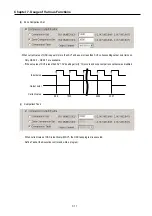
(b) External Preset
- Set external preset area and preset value.
- External devices are fixed as following
Ch0: IX0.0.4, Ch1: IX0.0.5, Ch2: IX0.0.6, Ch3: IX0.0.7
- Current value of high speed counter is replaced with preset value at the rising edge of external preset device.
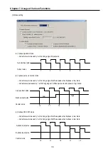
B-phase input pulse
Current value
A-phase input pulse
10 11 12 13 14 15 16 17 18 17 16 15 14 13
Summary of Contents for GLOFA G7M-DR20U
Page 28: ...Chapter 4 Names of Parts 4 3 2 G7M DRT60U N 3 G7M DT60U N 4 G7M DT60U P...
Page 29: ...Chapter 4 Names of Parts 4 4 5 G7M DR60U DC 6 G7M DRT60U N DC 7 G7M DT60U N DC...
Page 31: ...Chapter 4 Names of Parts 4 6 3 G7M DT40U N 4 G7M DT40U P 5 G7M DR40U DC...
Page 32: ...Chapter 4 Names of Parts 4 7 6 G7M DRT40U N DC 7 G7M DT40U N DC 8 G7M DT40U P DC...
Page 33: ...Chapter 4 Names of Parts 4 8 4 1 3 30 point main unit 1 G7M DR30U 2 G7M DRT30U N 3 G7M DT30U N...
Page 34: ...Chapter 4 Names of Parts 4 9 4 G7M DT30U P 5 G7M DR30U DC 6 G7M DRT30U N DC...
Page 36: ...Chapter 4 Names of Parts 4 11 2 G7M DRT20U N 3 G7M DT20U N 4 G7M DT20U P...
Page 37: ...Chapter 4 Names of Parts 4 12 5 G7M DR20U DC 6 G7M DRT20U N DC 7 G7M DT20U N DC...
Page 38: ...Chapter 4 Names of Parts 4 13 8 G7M DT20U P DC...
Page 159: ...Chapter 7 Usage of Various Functions 7 52 c Program...
Page 183: ...Chapter 7 Usage of Various Functions 7 76 c Program...
Page 253: ...Chapter 8 Communication Functions 8 27 b When uses Ch 1 Built in RS 485...
Page 356: ...Appendix 1 System Definitions App1 9 6 Position Parameter...
Page 357: ...Appendix 1 System Definitions App1 10 7 High Speed Counter Parameter...


