


Chapter 7. Usage of Various Functions
7-30
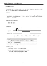
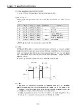
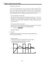
(10) Delta MV
This is useful to limit maximum change of manipulation value. For example, if
Δ
MV is set to 500, the MV value
in the operation scan does not change more than 500. The value should be set with proper value because the
speed could be reduced. Setting range is 0 ~ 4000 and default value is 4000.
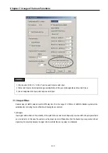
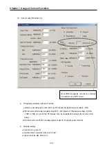
(11) Bias (%MW4810)
The Bias data is used for the compensation of offset in the proportional control. The range of input is 0 ~ 4000.
Be cautious that The actual range of Bias is –2000 ~ 2000. namely, 0~2000 represents 0 ~ +2000 and 2001 ~
4000 represents -1 ~ -2000.
Example)
If offset (SV-PV) is 100
→
Bias should be 100.
If offset (SV-PV) is -100
→
Bias should be 2100.
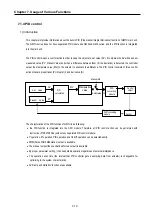
(12) SV(Target) and PV(Current)
SV (setting value: the designated value) and PV (process value: present value) of GM7U PID operation have
the range 0 ~ 4000. The range is set with the consideration of the resolution of A/D and D/A module of GM7U
series (12bits) and offset value.
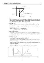
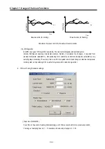
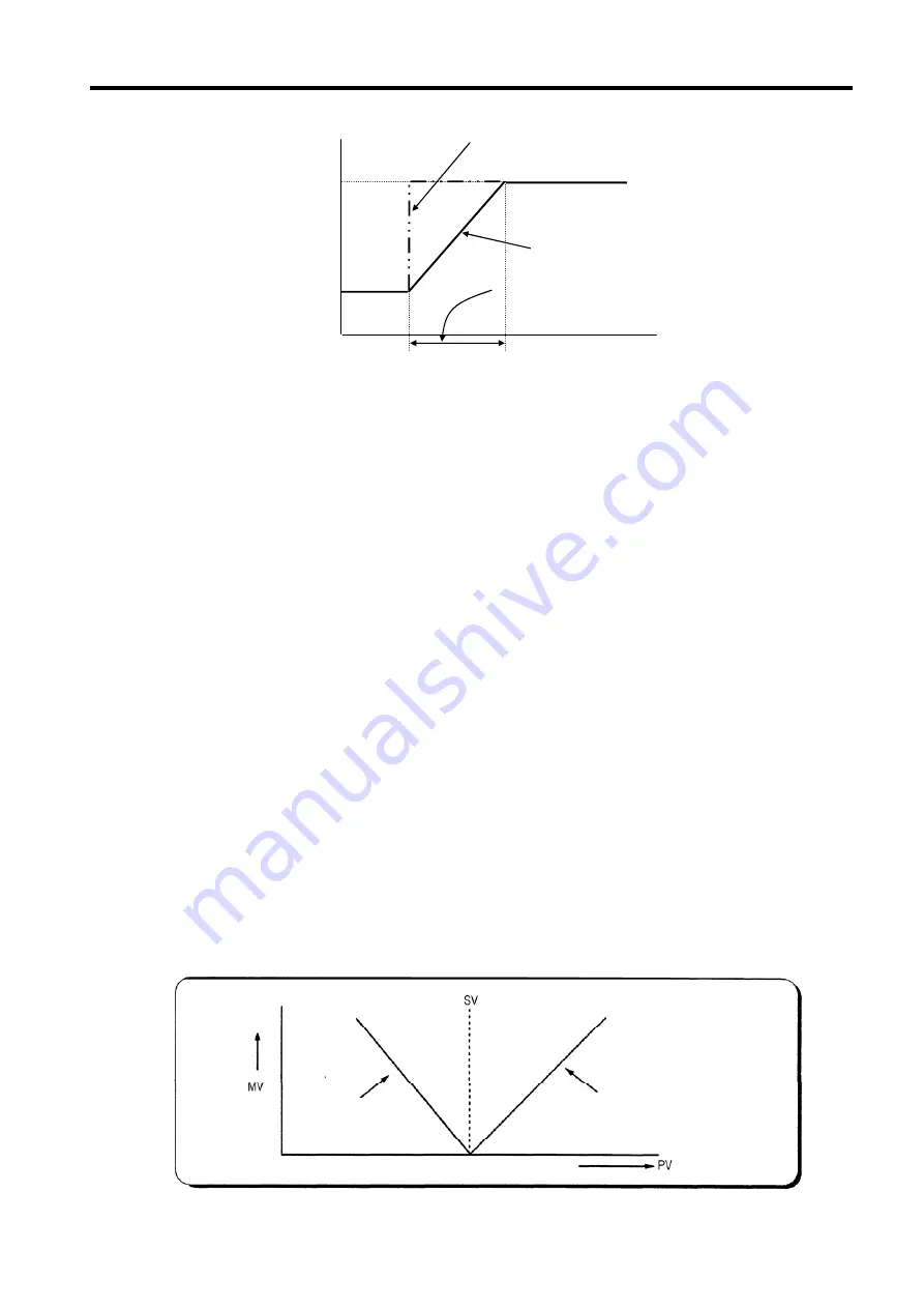
(13) Forward and reverse action
PID control has two kinds of action, forward action and reverse action.
- Forward action makes PV reach SV by outputting MV when PV is less than SV, the heating system is an
example of the forward action.
- Reverse action makes PV reach SV by outputting MV when PV is more than SV, the air cooling systems is an
example of the reverse action.
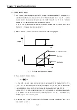
A diagram in which forward and reverse actions are drawn using MV, PV and SV is shown as below.
Forward and reverse action with MV, PV and SV
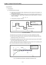
SV Ramp is designates
Time
Current SV
Changed SV
SV Ramp = 1
SV Ramp * Scan time
Forward action
Reverse action
Summary of Contents for GLOFA G7M-DR20U
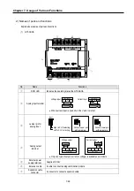
Page 28: ...Chapter 4 Names of Parts 4 3 2 G7M DRT60U N 3 G7M DT60U N 4 G7M DT60U P...
Page 29: ...Chapter 4 Names of Parts 4 4 5 G7M DR60U DC 6 G7M DRT60U N DC 7 G7M DT60U N DC...
Page 31: ...Chapter 4 Names of Parts 4 6 3 G7M DT40U N 4 G7M DT40U P 5 G7M DR40U DC...
Page 32: ...Chapter 4 Names of Parts 4 7 6 G7M DRT40U N DC 7 G7M DT40U N DC 8 G7M DT40U P DC...
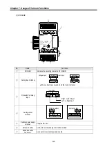
Page 33: ...Chapter 4 Names of Parts 4 8 4 1 3 30 point main unit 1 G7M DR30U 2 G7M DRT30U N 3 G7M DT30U N...
Page 34: ...Chapter 4 Names of Parts 4 9 4 G7M DT30U P 5 G7M DR30U DC 6 G7M DRT30U N DC...
Page 36: ...Chapter 4 Names of Parts 4 11 2 G7M DRT20U N 3 G7M DT20U N 4 G7M DT20U P...
Page 37: ...Chapter 4 Names of Parts 4 12 5 G7M DR20U DC 6 G7M DRT20U N DC 7 G7M DT20U N DC...
Page 38: ...Chapter 4 Names of Parts 4 13 8 G7M DT20U P DC...
Page 159: ...Chapter 7 Usage of Various Functions 7 52 c Program...
Page 183: ...Chapter 7 Usage of Various Functions 7 76 c Program...
Page 253: ...Chapter 8 Communication Functions 8 27 b When uses Ch 1 Built in RS 485...
Page 356: ...Appendix 1 System Definitions App1 9 6 Position Parameter...
Page 357: ...Appendix 1 System Definitions App1 10 7 High Speed Counter Parameter...


