


Chapter 7. Usage of Various Functions
7-32
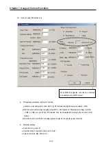
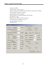
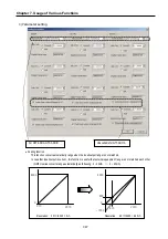
②
SV(set value) / PV (present value)
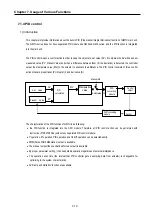
SV (set value: the designated value) and PV (process value: present value) of GM7U PID operation have the
range 0 ~ 4000. The range is set with the consideration of the resolution of A/D and D/A module of GM7U
series (12 bits) and offset value. When setting the SV or PV, please be careful convert the analog value of
control object (temperature, velocity, etc.) to digital value that are the output of A/D convert module.
ⓐ
When using sensor and A/D conversion module
Assume that PID control is used for temperature control with Pt100 (operation range: -200
°
C ~ 600
°
C), and
the goal value is 100
°
C. The equivalent digital output of A/D module (current input range: 4 ~ 20mA) is 1500
if the A/D module outputs 0 (4mA) with -200
°
C, and 4000(20mA) with 600
°
C. Therefore, the input of SV
should be 1500, not 100.
ⓑ
When using sensor and RTD module(G7F-RD2A)
Assume that PID control is used for temperature control with Pt100 (operation range: -200
°
C ~ 600
°
C), and
the goal value is 100
°
C. The digital output of RTD module is calculated as below.
2
2000
10
.
+
×
=
Temp
put
DigitalOut
Therefore, SV should be 1500,
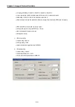
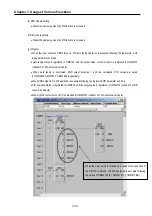
③
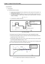
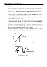
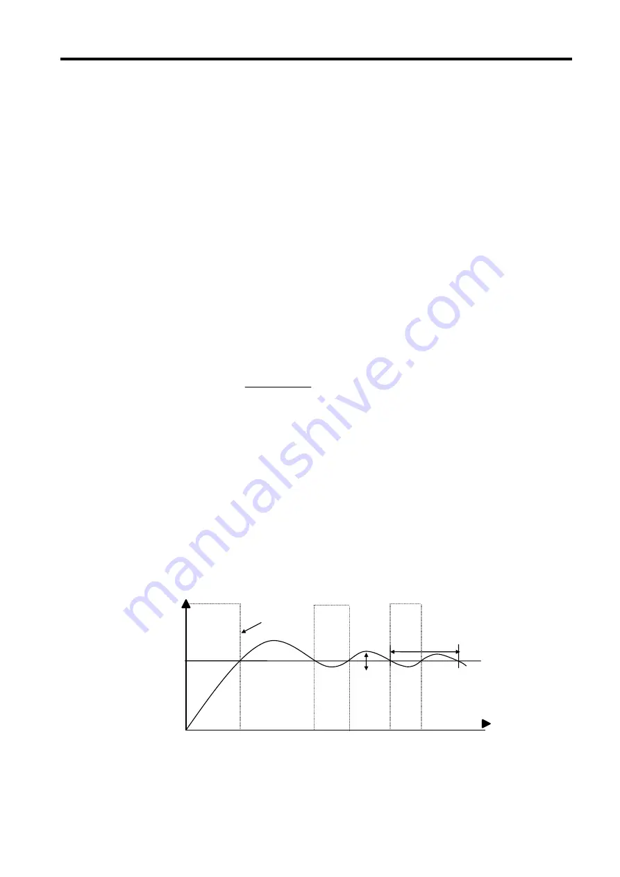
Tuning method
The GM7U perform auto-tuning operation in two methods. One is relay response method and the
other is process reaction curve method.
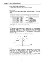
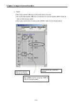
Relay
ⓐ
response method.
•
PID parameters are obtained by On/Off operation during 1 cycle of PV variation.
•
PID parameters are obtained by amplitude and period of oscillation
•
The On/Off operation will be occur at the SV value.
SV
Period
Amplitude
MV
Summary of Contents for GLOFA G7M-DR20U
Page 28: ...Chapter 4 Names of Parts 4 3 2 G7M DRT60U N 3 G7M DT60U N 4 G7M DT60U P...
Page 29: ...Chapter 4 Names of Parts 4 4 5 G7M DR60U DC 6 G7M DRT60U N DC 7 G7M DT60U N DC...
Page 31: ...Chapter 4 Names of Parts 4 6 3 G7M DT40U N 4 G7M DT40U P 5 G7M DR40U DC...
Page 32: ...Chapter 4 Names of Parts 4 7 6 G7M DRT40U N DC 7 G7M DT40U N DC 8 G7M DT40U P DC...
Page 33: ...Chapter 4 Names of Parts 4 8 4 1 3 30 point main unit 1 G7M DR30U 2 G7M DRT30U N 3 G7M DT30U N...
Page 34: ...Chapter 4 Names of Parts 4 9 4 G7M DT30U P 5 G7M DR30U DC 6 G7M DRT30U N DC...
Page 36: ...Chapter 4 Names of Parts 4 11 2 G7M DRT20U N 3 G7M DT20U N 4 G7M DT20U P...
Page 37: ...Chapter 4 Names of Parts 4 12 5 G7M DR20U DC 6 G7M DRT20U N DC 7 G7M DT20U N DC...
Page 38: ...Chapter 4 Names of Parts 4 13 8 G7M DT20U P DC...
Page 159: ...Chapter 7 Usage of Various Functions 7 52 c Program...
Page 183: ...Chapter 7 Usage of Various Functions 7 76 c Program...
Page 253: ...Chapter 8 Communication Functions 8 27 b When uses Ch 1 Built in RS 485...
Page 356: ...Appendix 1 System Definitions App1 9 6 Position Parameter...
Page 357: ...Appendix 1 System Definitions App1 10 7 High Speed Counter Parameter...


