


Chapter 7. Usage of Various Functions
7-58
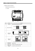
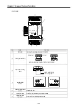
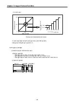
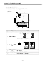
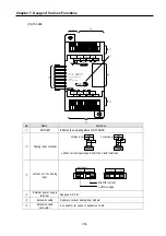
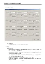
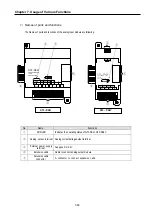
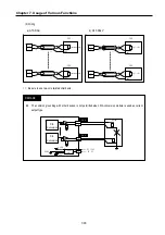
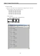
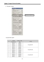
(2) Wiring
*1: Be sure to use two-core twisted shield wire.
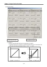
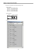
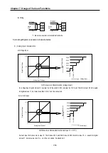
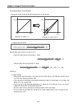
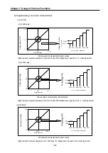
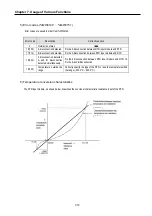
5) Analog/Digital conversion characteristics
(1)
Analog input characteristics
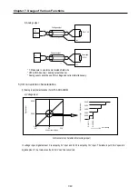
a) Voltage input
In voltage input, digital amount 0 is output by 0V input and 4,000 is output by 10V input. Therefore input 2.5mV equals
to digital amount 1, but value less than 2.5mV can’t be converted.
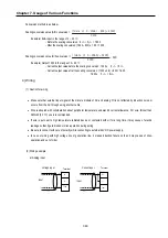
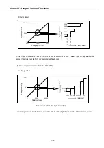
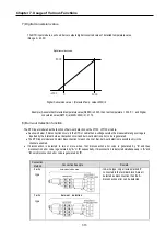
b) Current input
Current input 0mA becomes output 0, 10mA does 2000 and 20mA does 4000. therefore input 5
㎂
equals to digital
amount 1, but value less tan 5
㎂
can’t be converted. So abandon it.
Digit
al Out
put V
alue
Digit
al Out
put V
alue
2004
2002
2001
2000
2003
5.
000V
5.
0025V
Voltage Input
Digit
al Out
put V
alue
4000
2000
0
0V
5V
10V
Analog Input Voltage
A/D Conversion Characteristics (Voltage Input)
2004
2002
2001
2000
2003
10.
000
㎃
10.
005
㎃
4000
2000
0
0 ㎃
10 ㎃
20 ㎃
A/D Conversion Characteristics (Current Input 0
∼
20
㎃
)
Analog
Input
+
-
+
-
Analog
Input
Voltage
Current
V0
I0
COM0
V1
I1
COM1
Terminal
Terminal
*1
*1
Digit
al Out
put V
alue
Analog Input Current
Current Input
Summary of Contents for GLOFA G7M-DR20U
Page 28: ...Chapter 4 Names of Parts 4 3 2 G7M DRT60U N 3 G7M DT60U N 4 G7M DT60U P...
Page 29: ...Chapter 4 Names of Parts 4 4 5 G7M DR60U DC 6 G7M DRT60U N DC 7 G7M DT60U N DC...
Page 31: ...Chapter 4 Names of Parts 4 6 3 G7M DT40U N 4 G7M DT40U P 5 G7M DR40U DC...
Page 32: ...Chapter 4 Names of Parts 4 7 6 G7M DRT40U N DC 7 G7M DT40U N DC 8 G7M DT40U P DC...
Page 33: ...Chapter 4 Names of Parts 4 8 4 1 3 30 point main unit 1 G7M DR30U 2 G7M DRT30U N 3 G7M DT30U N...
Page 34: ...Chapter 4 Names of Parts 4 9 4 G7M DT30U P 5 G7M DR30U DC 6 G7M DRT30U N DC...
Page 36: ...Chapter 4 Names of Parts 4 11 2 G7M DRT20U N 3 G7M DT20U N 4 G7M DT20U P...
Page 37: ...Chapter 4 Names of Parts 4 12 5 G7M DR20U DC 6 G7M DRT20U N DC 7 G7M DT20U N DC...
Page 38: ...Chapter 4 Names of Parts 4 13 8 G7M DT20U P DC...
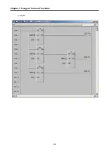
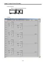
Page 159: ...Chapter 7 Usage of Various Functions 7 52 c Program...
Page 183: ...Chapter 7 Usage of Various Functions 7 76 c Program...
Page 253: ...Chapter 8 Communication Functions 8 27 b When uses Ch 1 Built in RS 485...
Page 356: ...Appendix 1 System Definitions App1 9 6 Position Parameter...
Page 357: ...Appendix 1 System Definitions App1 10 7 High Speed Counter Parameter...


