


Chapter 7. Usage of Various Functions
7-67
.
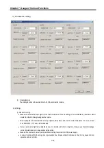
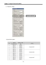
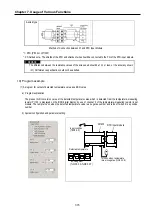
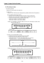
7) Program example
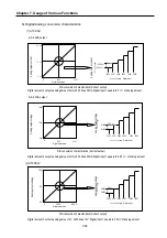
(1) Program which controls speed of inverter by analog output current (or voltage) of 5 steps (0 ~ 20mA /0~10V)
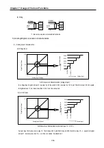
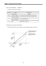
a) Program explanation (0 channel of the expansion module no.1)
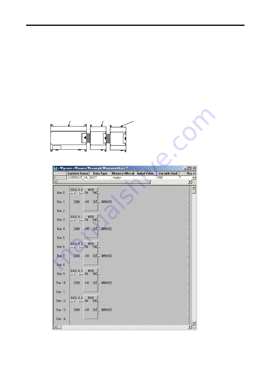
- When %QX0.0.0 is On, 2000(10
㎃
/5V) is output.
- When %QX0.0.1 is On, 2400(12
㎃
/6V) is output.
- When %QX0.0.2 is On, 2800(14
㎃
/7V) is output.
- When %QX0.0.3 is On, 3200(16
㎃
/8V) is output.
- When %QX0.0.4 is On, 3600(18
㎃
/9V) is output.
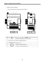
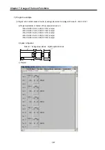
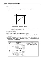
b) System configuration
Main unit Analog output module Digital expansion module
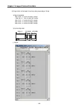
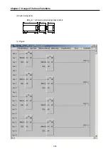
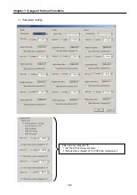
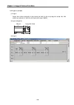
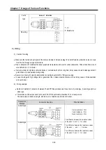
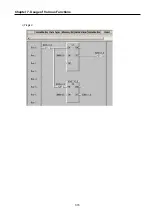
c)
Program
Summary of Contents for GLOFA G7M-DR20U
Page 28: ...Chapter 4 Names of Parts 4 3 2 G7M DRT60U N 3 G7M DT60U N 4 G7M DT60U P...
Page 29: ...Chapter 4 Names of Parts 4 4 5 G7M DR60U DC 6 G7M DRT60U N DC 7 G7M DT60U N DC...
Page 31: ...Chapter 4 Names of Parts 4 6 3 G7M DT40U N 4 G7M DT40U P 5 G7M DR40U DC...
Page 32: ...Chapter 4 Names of Parts 4 7 6 G7M DRT40U N DC 7 G7M DT40U N DC 8 G7M DT40U P DC...
Page 33: ...Chapter 4 Names of Parts 4 8 4 1 3 30 point main unit 1 G7M DR30U 2 G7M DRT30U N 3 G7M DT30U N...
Page 34: ...Chapter 4 Names of Parts 4 9 4 G7M DT30U P 5 G7M DR30U DC 6 G7M DRT30U N DC...
Page 36: ...Chapter 4 Names of Parts 4 11 2 G7M DRT20U N 3 G7M DT20U N 4 G7M DT20U P...
Page 37: ...Chapter 4 Names of Parts 4 12 5 G7M DR20U DC 6 G7M DRT20U N DC 7 G7M DT20U N DC...
Page 38: ...Chapter 4 Names of Parts 4 13 8 G7M DT20U P DC...
Page 159: ...Chapter 7 Usage of Various Functions 7 52 c Program...
Page 183: ...Chapter 7 Usage of Various Functions 7 76 c Program...
Page 253: ...Chapter 8 Communication Functions 8 27 b When uses Ch 1 Built in RS 485...
Page 356: ...Appendix 1 System Definitions App1 9 6 Position Parameter...
Page 357: ...Appendix 1 System Definitions App1 10 7 High Speed Counter Parameter...


