


Chapter 7. Usage of Various Functions
7-73
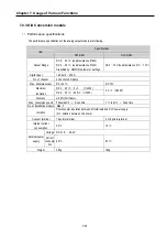
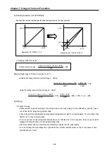
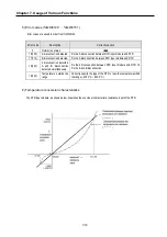
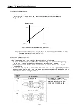
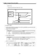
7) Digital conversion value
The RTD input module, as shown below, outputs digital converted value of detected temperature value.
(Range 0 ~ 4000)
Digital Conversion value = (Detected Temp. value+2000)/2
Example) Assume that Detected temperature value(D4980) is 2345, then real temperature = 234.5
℃
, and Digital
conversion value(D4770) is (2345+2000)/2 = 2172.
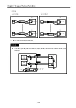
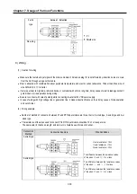
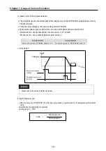
8) Burn-out detection function
The RTD input module has the function of burn-out detection on the Pt100, JPt100 or cable.
•
As shown below, if disconnection occurs in the RTD or cable then a voltage outside the measurable range voltage is
inputted by the internal burn-out detection circuit and burn-out detection error code is generated.
•
The RTD input module can detect disconnection for each channel. But, burn-out detection is possible only in the
channels enabled.
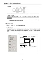
•
If disconnection is detected in two or more wires, first, disconnection error code is generated by
‘b’
and then
disconnection error code is generated by
‘A’
or
‘b’
sequentially. If disconnection is detected simultaneously in
‘A’
and
‘B
’, only disconnection error code is generated by
‘b’
.
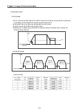
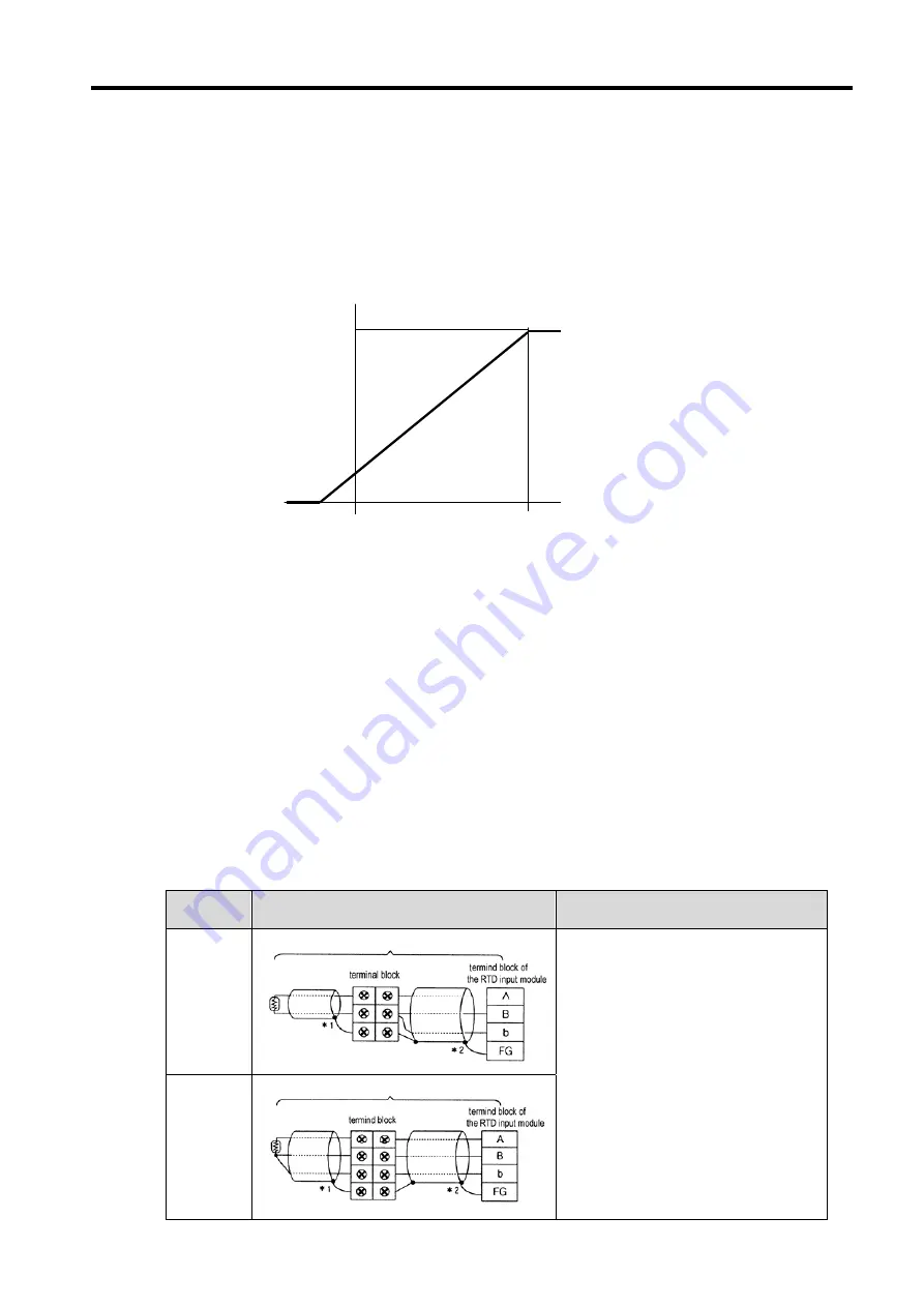
Connection
Method
Connection Example
Remark
2-wire
type
3-wire
type
- In 4-wire type, only all wires marked '2'
connected to the terminal block A are all
detected as disconnection then the A
disconnection error can be detected.
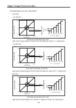
4000
-2000
6000
Digital conversion value
0
burn-out detection
burn-out detection area
Summary of Contents for GLOFA G7M-DR20U
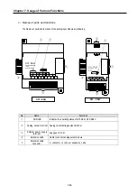
Page 28: ...Chapter 4 Names of Parts 4 3 2 G7M DRT60U N 3 G7M DT60U N 4 G7M DT60U P...
Page 29: ...Chapter 4 Names of Parts 4 4 5 G7M DR60U DC 6 G7M DRT60U N DC 7 G7M DT60U N DC...
Page 31: ...Chapter 4 Names of Parts 4 6 3 G7M DT40U N 4 G7M DT40U P 5 G7M DR40U DC...
Page 32: ...Chapter 4 Names of Parts 4 7 6 G7M DRT40U N DC 7 G7M DT40U N DC 8 G7M DT40U P DC...
Page 33: ...Chapter 4 Names of Parts 4 8 4 1 3 30 point main unit 1 G7M DR30U 2 G7M DRT30U N 3 G7M DT30U N...
Page 34: ...Chapter 4 Names of Parts 4 9 4 G7M DT30U P 5 G7M DR30U DC 6 G7M DRT30U N DC...
Page 36: ...Chapter 4 Names of Parts 4 11 2 G7M DRT20U N 3 G7M DT20U N 4 G7M DT20U P...
Page 37: ...Chapter 4 Names of Parts 4 12 5 G7M DR20U DC 6 G7M DRT20U N DC 7 G7M DT20U N DC...
Page 38: ...Chapter 4 Names of Parts 4 13 8 G7M DT20U P DC...
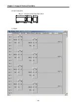
Page 159: ...Chapter 7 Usage of Various Functions 7 52 c Program...
Page 183: ...Chapter 7 Usage of Various Functions 7 76 c Program...
Page 253: ...Chapter 8 Communication Functions 8 27 b When uses Ch 1 Built in RS 485...
Page 356: ...Appendix 1 System Definitions App1 9 6 Position Parameter...
Page 357: ...Appendix 1 System Definitions App1 10 7 High Speed Counter Parameter...


