


Chapter 7. Usage of Various Functions
7-81
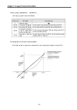
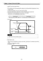
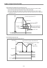
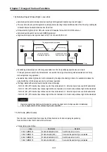
(2) Speed Control (Uniform Speed Operation)
•
This controls the speed by the setting speed until deceleration stop command(POSCTR) is entered after execution by
POSVEL command..
•
The speed can be changed by the speed override instruction(POSSOR)
•
Speed control contains 2 types of start method : Forward direction start and Reverse direction start.
- Forward direction : when position address is positive number (+) (“0” included)
- Reverse direction : when position address is negative number (-)
Forward direction
Reverse direction
Set second operand of POSVEL instruction to 0 Set second operand of POSVEL instruction to 1
•
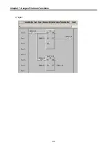
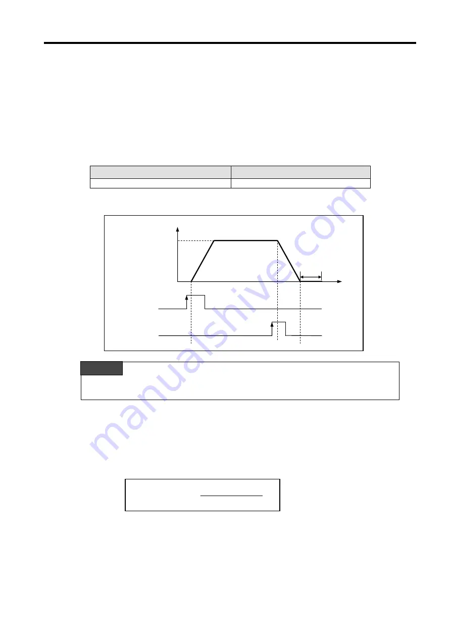
Timing diagram
Please refer to the section ‘POSVEL’ for details.
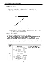
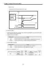
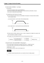
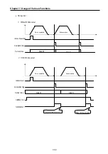
(3) Synchronization control
•
After the execution of POSSYNC, the HSC input pulse speed is synchronized by the designated synchronization
scale.
•
Scale can be changed during the execution.
•
Setting range: 0 ~ 100%
Speed
On
Time
On
Setting speed
Dwell time
Deceleration stop command
(POSCTR)
Speed control command
(POSVEL)
REMARK
Scale =
Positioning speed
HSC input speed
Summary of Contents for GLOFA G7M-DR20U
Page 28: ...Chapter 4 Names of Parts 4 3 2 G7M DRT60U N 3 G7M DT60U N 4 G7M DT60U P...
Page 29: ...Chapter 4 Names of Parts 4 4 5 G7M DR60U DC 6 G7M DRT60U N DC 7 G7M DT60U N DC...
Page 31: ...Chapter 4 Names of Parts 4 6 3 G7M DT40U N 4 G7M DT40U P 5 G7M DR40U DC...
Page 32: ...Chapter 4 Names of Parts 4 7 6 G7M DRT40U N DC 7 G7M DT40U N DC 8 G7M DT40U P DC...
Page 33: ...Chapter 4 Names of Parts 4 8 4 1 3 30 point main unit 1 G7M DR30U 2 G7M DRT30U N 3 G7M DT30U N...
Page 34: ...Chapter 4 Names of Parts 4 9 4 G7M DT30U P 5 G7M DR30U DC 6 G7M DRT30U N DC...
Page 36: ...Chapter 4 Names of Parts 4 11 2 G7M DRT20U N 3 G7M DT20U N 4 G7M DT20U P...
Page 37: ...Chapter 4 Names of Parts 4 12 5 G7M DR20U DC 6 G7M DRT20U N DC 7 G7M DT20U N DC...
Page 38: ...Chapter 4 Names of Parts 4 13 8 G7M DT20U P DC...
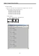
Page 159: ...Chapter 7 Usage of Various Functions 7 52 c Program...
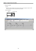
Page 183: ...Chapter 7 Usage of Various Functions 7 76 c Program...
Page 253: ...Chapter 8 Communication Functions 8 27 b When uses Ch 1 Built in RS 485...
Page 356: ...Appendix 1 System Definitions App1 9 6 Position Parameter...
Page 357: ...Appendix 1 System Definitions App1 10 7 High Speed Counter Parameter...


