


Chapter 7. Usage of Various Functions
7-94
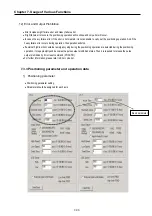
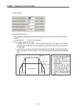
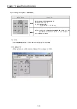
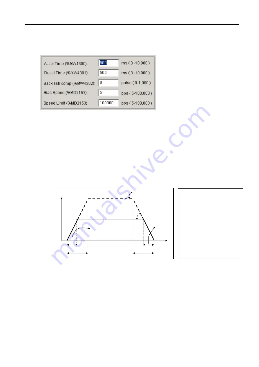
(1) Basic parameter
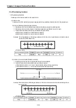
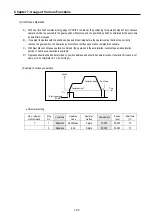
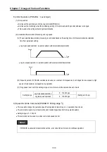
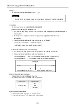
(A) Acceleration/Deceleration time
•
This is applied at the starting/ending point of positioning operation, return to origin high speed, and JOG high speed
operation
•
The setting range is 0
∼
10,000 (unit: 1ms) for each axis.
•
When set to zero, operates constant speed.
①
Acceleration time : the time required to reach from speed “0”(stop state) to the speed limit which is set by
parameter. In case of using BIAS, it is the time required to reach from the bias speed to the speed limit which is
set by parameter.
②
Deceleration time : the time required to reach from the speed limit set by parameter to the speed “0”(stop state).
In case of using BIAS, it is the time required to reach from the speed limit set by parameter to the setting bias
speed.
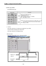
Actual
deceleration time
Acceleration
time
Actual acceleration time
Time
Setting speed
Speed limit
Speed
Deceleration
time
- Speed limit : max. speed available
to set for positioning operation at
the parameter of GMWIN.
- Setting speed : speed value of
operation data that position data
operates actually.
- Actual acceleration time : the time
required to reach from speed
“0”(stop state) to the speed value
which is set by operation data.
- Actual deceleration time : the time
required to reach from the speed
value set by operation data to
speed
Summary of Contents for GLOFA G7M-DR20U
Page 28: ...Chapter 4 Names of Parts 4 3 2 G7M DRT60U N 3 G7M DT60U N 4 G7M DT60U P...
Page 29: ...Chapter 4 Names of Parts 4 4 5 G7M DR60U DC 6 G7M DRT60U N DC 7 G7M DT60U N DC...
Page 31: ...Chapter 4 Names of Parts 4 6 3 G7M DT40U N 4 G7M DT40U P 5 G7M DR40U DC...
Page 32: ...Chapter 4 Names of Parts 4 7 6 G7M DRT40U N DC 7 G7M DT40U N DC 8 G7M DT40U P DC...
Page 33: ...Chapter 4 Names of Parts 4 8 4 1 3 30 point main unit 1 G7M DR30U 2 G7M DRT30U N 3 G7M DT30U N...
Page 34: ...Chapter 4 Names of Parts 4 9 4 G7M DT30U P 5 G7M DR30U DC 6 G7M DRT30U N DC...
Page 36: ...Chapter 4 Names of Parts 4 11 2 G7M DRT20U N 3 G7M DT20U N 4 G7M DT20U P...
Page 37: ...Chapter 4 Names of Parts 4 12 5 G7M DR20U DC 6 G7M DRT20U N DC 7 G7M DT20U N DC...
Page 38: ...Chapter 4 Names of Parts 4 13 8 G7M DT20U P DC...
Page 159: ...Chapter 7 Usage of Various Functions 7 52 c Program...
Page 183: ...Chapter 7 Usage of Various Functions 7 76 c Program...
Page 253: ...Chapter 8 Communication Functions 8 27 b When uses Ch 1 Built in RS 485...
Page 356: ...Appendix 1 System Definitions App1 9 6 Position Parameter...
Page 357: ...Appendix 1 System Definitions App1 10 7 High Speed Counter Parameter...


