


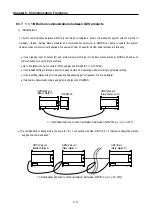
Chapter 8. Communication Functions
8-11
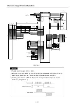
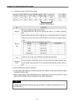
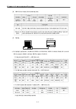
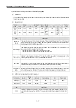
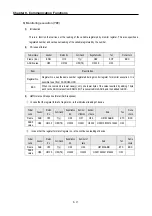
(4)
GM7U main unit response format (NAK response)
Format name
Header
Station
No.
Command
Command type
Error code
(Hex 2 Byte)
Tail
Frame check
Frame (Ex.)
NAK
H20
R(r)
SS
H1132
ETX
BCC
ACSII value
H15
H3230
H52(72) H5353 H31313332 H03
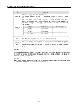
Item
Description
Error code
Hex and 2 bytes (ASCII code, 4 bytes) indicate error type. For the details, see 8.1.8 Error codes.
Frame check
(BCC)
When command is lowercase(r), only one lower byte of the value resulted by adding 1 byte each
to the ASCII values from NAK to ETX is converted into ASCII and added to BCC.
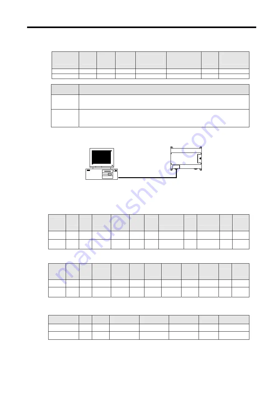
(5)
Example
•
This example assumes when 1 WORD from %MW20, and 1 WORD from %QW0.0.1 address of station No.1 are read.
H1234 is entered in %MW20, and data of H5678 is entered in %QW0.0.1.
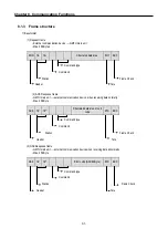
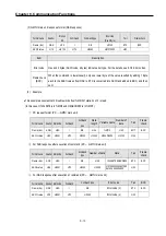
①
Computer request format (PC
→
GM7U main unit)
Format
name
Header Station
No.
Command Command
type
Number
of
blocks
Variable
length
Format name Device
length
Format name Tail
Frame
check
Frame ENQ H01
r
SS H02 H05 %MW20 H08 %QW0.0.1 EOT BCC
ACSII
value
H05 H3031 H72
H5353 H3032 H3035 H254D573230 H3038
H25515730
2E302E31
H04
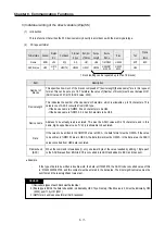
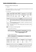
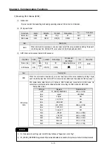
②
For ACK response after execution of command (PC
←
GM7U main unit)
Format
name
Header Station
No.
Command Command
type
Number
of
blocks
Variable
length
Format
name
Device
length
Format
name
Tail
Frame
check
Frame ACK H01
r
SS H02 H02 H1234 H02 H5678 ETX BCC
ACSII
value
H06 H3031 H72
H5353 H3032
H3032 H31323334 H3032 H35363738 H03
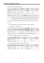
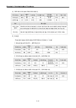
③
For NAK response after execution of command (PC
←
GM7U main unit)
Format name
Header Station No.
Command
Command type
Error code
Tail
Frame check
Frame
NAK
H01
r
SS
Error code (2)
ETX
BCC
ACSII value
H15
H3031
H72
H5353
Error code (4)
H03
※
Frame check BCC is automatically operated.
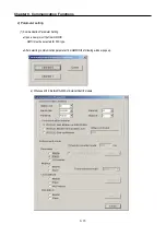
GM7U main unit
Summary of Contents for GLOFA G7M-DR20U
Page 28: ...Chapter 4 Names of Parts 4 3 2 G7M DRT60U N 3 G7M DT60U N 4 G7M DT60U P...
Page 29: ...Chapter 4 Names of Parts 4 4 5 G7M DR60U DC 6 G7M DRT60U N DC 7 G7M DT60U N DC...
Page 31: ...Chapter 4 Names of Parts 4 6 3 G7M DT40U N 4 G7M DT40U P 5 G7M DR40U DC...
Page 32: ...Chapter 4 Names of Parts 4 7 6 G7M DRT40U N DC 7 G7M DT40U N DC 8 G7M DT40U P DC...
Page 33: ...Chapter 4 Names of Parts 4 8 4 1 3 30 point main unit 1 G7M DR30U 2 G7M DRT30U N 3 G7M DT30U N...
Page 34: ...Chapter 4 Names of Parts 4 9 4 G7M DT30U P 5 G7M DR30U DC 6 G7M DRT30U N DC...
Page 36: ...Chapter 4 Names of Parts 4 11 2 G7M DRT20U N 3 G7M DT20U N 4 G7M DT20U P...
Page 37: ...Chapter 4 Names of Parts 4 12 5 G7M DR20U DC 6 G7M DRT20U N DC 7 G7M DT20U N DC...
Page 38: ...Chapter 4 Names of Parts 4 13 8 G7M DT20U P DC...
Page 159: ...Chapter 7 Usage of Various Functions 7 52 c Program...
Page 183: ...Chapter 7 Usage of Various Functions 7 76 c Program...
Page 253: ...Chapter 8 Communication Functions 8 27 b When uses Ch 1 Built in RS 485...
Page 356: ...Appendix 1 System Definitions App1 9 6 Position Parameter...
Page 357: ...Appendix 1 System Definitions App1 10 7 High Speed Counter Parameter...


