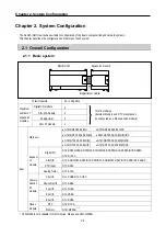
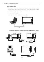
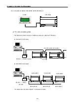


Chapter 3. General Specifications
3-1
Chapter 3.
General Specifications
3.1 General Specifications
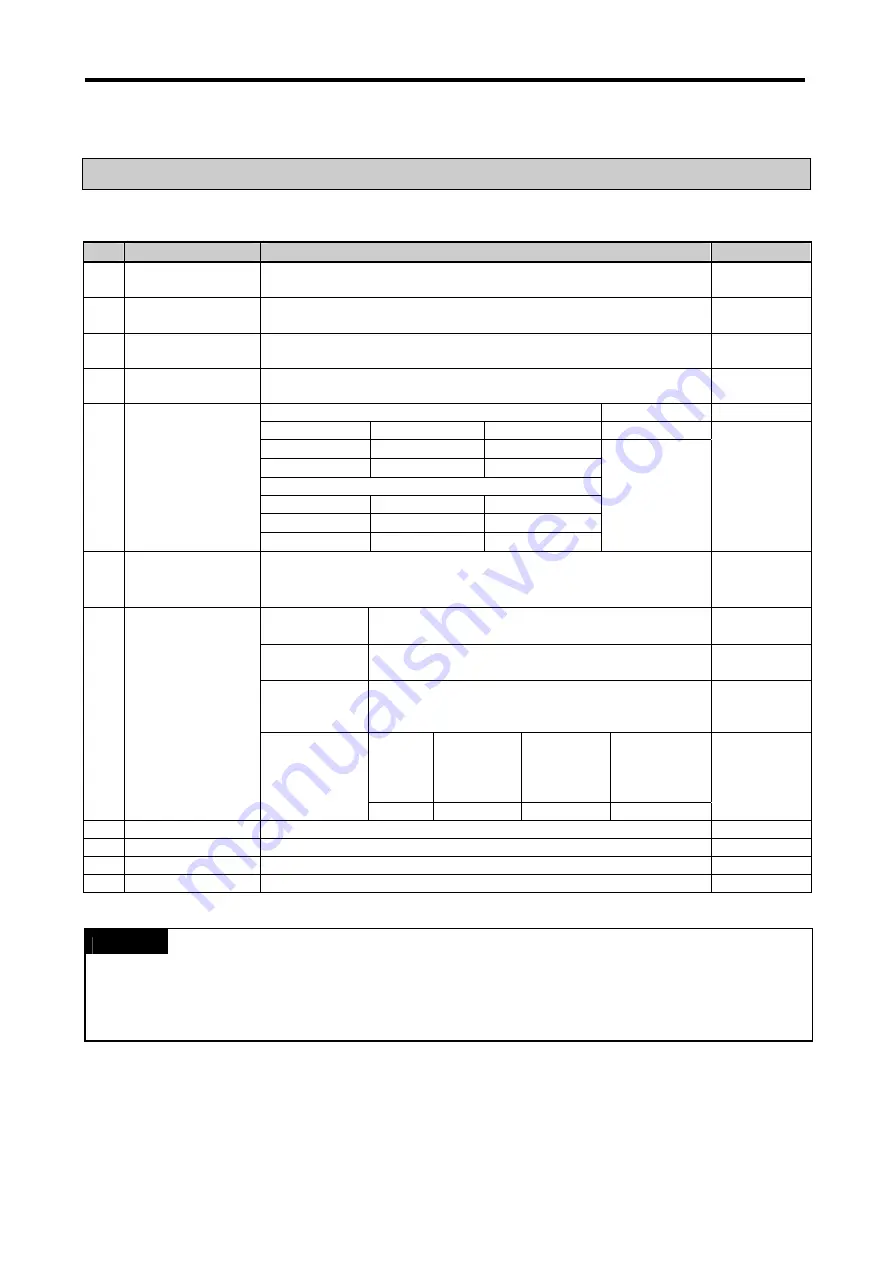
The following shows the general specifications of the GLOFA-GM series.
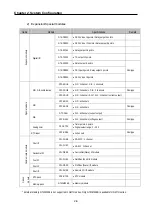
No.
Item
Specifications
References
1
Operating ambient
temperature
0 ~ 55
°
C
2
Storage ambient
temperature
−
25 ~
+
70
°
C
3
Operating ambient
humidity
5 ~ 95%RH, non-condensing
4
Storage ambient
humidity
5 ~ 95%RH, non-condensing
Occasional vibration
-
Frequency Acceleration Amplitude Sweep
count
10
≤
f
<
57Hz
−
0.075mm
57
≤
f
≤
150Hz
9.8m/s
2
{1G}
−
Continuous vibration
Frequency Acceleration Amplitude
10
≤
f
<
57Hz
−
0.0375mm
5 Vibrations
57
≤
f
≤
150Hz
4.9m/s
2
{0.5G}
−
10 times for each
X, Y, Z axis
IEC 61131-2
6 Shocks
•
Maximum shock acceleration: 147 m/s
2
{15G}
•
Duration time: 11ms
•
Pulse wave: half sine pulse (3 shocks per axis, on X, Y, Z axis)
IEC 61131-2
Square wave
Impulse noise
±
1,500 V
LSIS’ Standard
Electronic
discharge
Voltage: 4 kV (Discharge by contact)
IEC 61131-2,
IEC 1000-1-2
Radiated
electromagnetic
field noise
27 ~ 500 MHz, 10 V/m
IEC 61131-2,
IEC 1000-1-3
Item
Power
supply
Digital I/O
(>24V)
Digital I/O
(<24V)
Analog I/O
Interface
7 Noise
immunity
Fast transient
/burst noise
Voltage 2kV
1kV
0.25kV
IEC 61131-2
IEC 1000-1-4
8
Atmosphere
Free of corrosive gases and excessive dust
9
Altitude
Up to 2,000m
10
Pollution degree
Below 2
11 Cooling
method
Air-cooling
REMARK
1) IEC (International Electro-technical Commission): An international non-governmental organization enacting international
standards of electric and electronic fields.
2) Pollution degree: Index indicating the pollution of operating environment to determine the insulation capacity of equipment.
Pollution degree 2: Normally only nonconductive pollution occurs. Temporary conductivity caused by condensation is to be
expected.
Summary of Contents for GLOFA G7M-DR20U
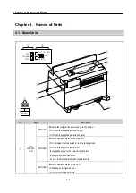
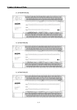
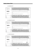
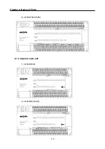
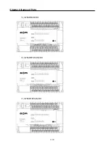
Page 28: ...Chapter 4 Names of Parts 4 3 2 G7M DRT60U N 3 G7M DT60U N 4 G7M DT60U P...
Page 29: ...Chapter 4 Names of Parts 4 4 5 G7M DR60U DC 6 G7M DRT60U N DC 7 G7M DT60U N DC...
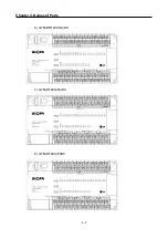
Page 31: ...Chapter 4 Names of Parts 4 6 3 G7M DT40U N 4 G7M DT40U P 5 G7M DR40U DC...
Page 32: ...Chapter 4 Names of Parts 4 7 6 G7M DRT40U N DC 7 G7M DT40U N DC 8 G7M DT40U P DC...
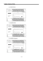
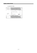
Page 33: ...Chapter 4 Names of Parts 4 8 4 1 3 30 point main unit 1 G7M DR30U 2 G7M DRT30U N 3 G7M DT30U N...
Page 34: ...Chapter 4 Names of Parts 4 9 4 G7M DT30U P 5 G7M DR30U DC 6 G7M DRT30U N DC...
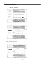
Page 36: ...Chapter 4 Names of Parts 4 11 2 G7M DRT20U N 3 G7M DT20U N 4 G7M DT20U P...
Page 37: ...Chapter 4 Names of Parts 4 12 5 G7M DR20U DC 6 G7M DRT20U N DC 7 G7M DT20U N DC...
Page 38: ...Chapter 4 Names of Parts 4 13 8 G7M DT20U P DC...
Page 159: ...Chapter 7 Usage of Various Functions 7 52 c Program...
Page 183: ...Chapter 7 Usage of Various Functions 7 76 c Program...
Page 253: ...Chapter 8 Communication Functions 8 27 b When uses Ch 1 Built in RS 485...
Page 356: ...Appendix 1 System Definitions App1 9 6 Position Parameter...
Page 357: ...Appendix 1 System Definitions App1 10 7 High Speed Counter Parameter...


