


Chapter 8. Communication Functions
8-28
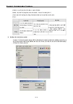
•
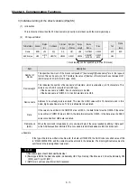
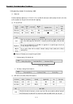
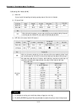
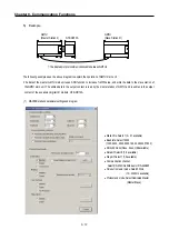
Set according to the following table
Item
Descriptions
Station No.
Sets one of station from 0 to 31.
Baud rate
Sets one of 1200, 2400, 4800, 9600, 19200, 38400, 57600 bps
Data bit
Sets one of 7 or 8 Bits
Parity bit
Sets one of none, Even, Odd
Stop bit
Sets one of 1 or 2 Bit(s)
Communication
channel
•
RS232C null modem or RS422/485: can be selected as a communication channel when
communication is processed by built-in functions of GM7U Main unit or Cnet I/F module (G7L-
CUEC).
•
RS232C dedicated modem: can be selected when communication is processed by Cnet I/F
module (G7L-CUEC).
•
RS232C dial-up modem: can be selected when common modem communication calling the
opponent station is processed by Cnet I/F module (G7L-CUEC).
* Notes: RS232C dedicated modem and RS232C dial-up modem communication can be processed only
by
Cnet I/F module (G7L-CUEC) support RS-232C, not Cnet I/F module (G7L-CUEC) supporting RS-
422/485.
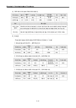
Timeout in
Master Mode
•
It’s an interval waiting after sending request frame from GM7U before receiving a response.
•
Default value is 500ms.
•
Setting must be done in consideration of maximum interval of sending and receiving cycle of a
master PLC.
•
If the time out is less than the maximum interval of the s/r cycle, error can occur.
Dedicated
Master/Slave
GM7U can read from and write on Slave GM7U.
Read status of
slave PLC
Can be select especially when you read Slave GM7U for monitoring, but not for the other
purposes, lest it may cause decreasing communication speed.
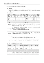
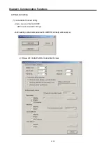
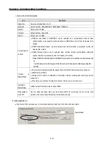
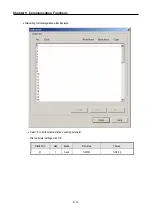
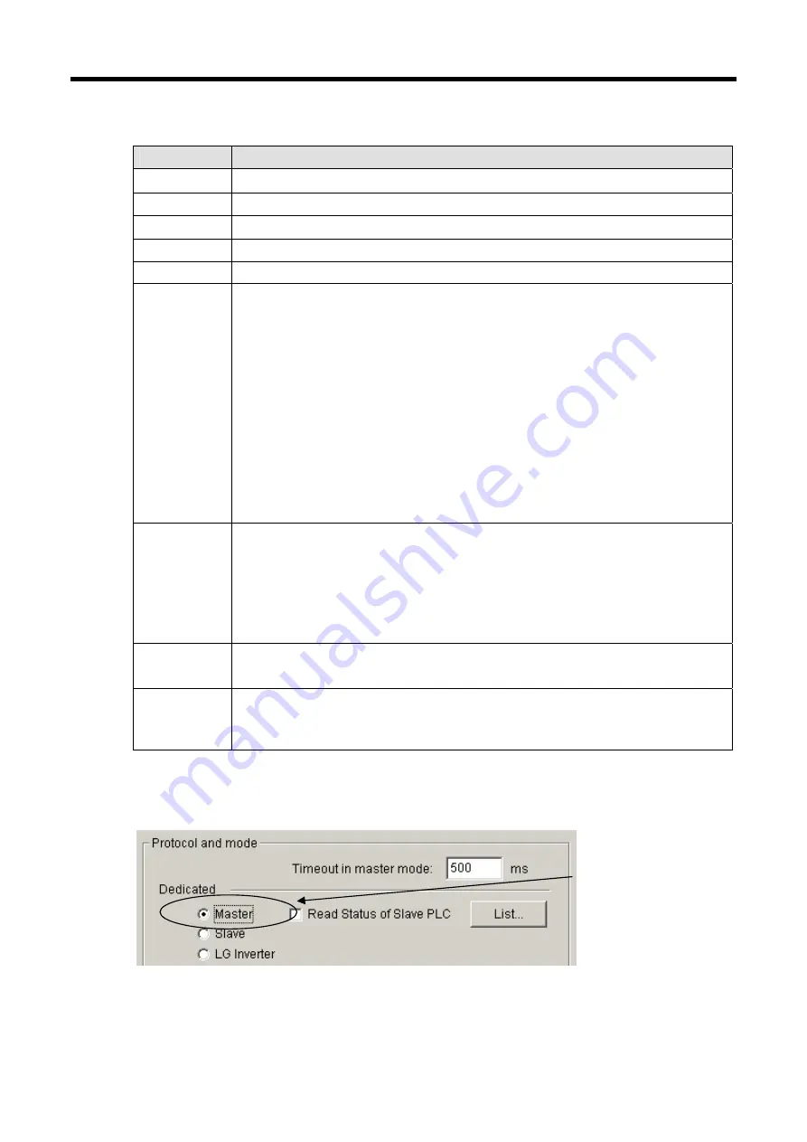
(2) Setting registration list
•
Click 'master' from 'exclusive use' in 'protocol and sending mode' then 'List' button will be activated.
Select Master
Summary of Contents for GLOFA G7M-DR20U
Page 28: ...Chapter 4 Names of Parts 4 3 2 G7M DRT60U N 3 G7M DT60U N 4 G7M DT60U P...
Page 29: ...Chapter 4 Names of Parts 4 4 5 G7M DR60U DC 6 G7M DRT60U N DC 7 G7M DT60U N DC...
Page 31: ...Chapter 4 Names of Parts 4 6 3 G7M DT40U N 4 G7M DT40U P 5 G7M DR40U DC...
Page 32: ...Chapter 4 Names of Parts 4 7 6 G7M DRT40U N DC 7 G7M DT40U N DC 8 G7M DT40U P DC...
Page 33: ...Chapter 4 Names of Parts 4 8 4 1 3 30 point main unit 1 G7M DR30U 2 G7M DRT30U N 3 G7M DT30U N...
Page 34: ...Chapter 4 Names of Parts 4 9 4 G7M DT30U P 5 G7M DR30U DC 6 G7M DRT30U N DC...
Page 36: ...Chapter 4 Names of Parts 4 11 2 G7M DRT20U N 3 G7M DT20U N 4 G7M DT20U P...
Page 37: ...Chapter 4 Names of Parts 4 12 5 G7M DR20U DC 6 G7M DRT20U N DC 7 G7M DT20U N DC...
Page 38: ...Chapter 4 Names of Parts 4 13 8 G7M DT20U P DC...
Page 159: ...Chapter 7 Usage of Various Functions 7 52 c Program...
Page 183: ...Chapter 7 Usage of Various Functions 7 76 c Program...
Page 253: ...Chapter 8 Communication Functions 8 27 b When uses Ch 1 Built in RS 485...
Page 356: ...Appendix 1 System Definitions App1 9 6 Position Parameter...
Page 357: ...Appendix 1 System Definitions App1 10 7 High Speed Counter Parameter...


