


Chapter 8. Communication Functions
8-46
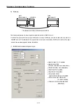
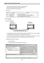
•
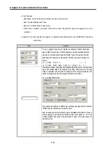
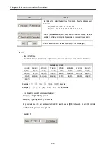
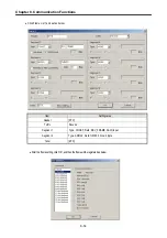
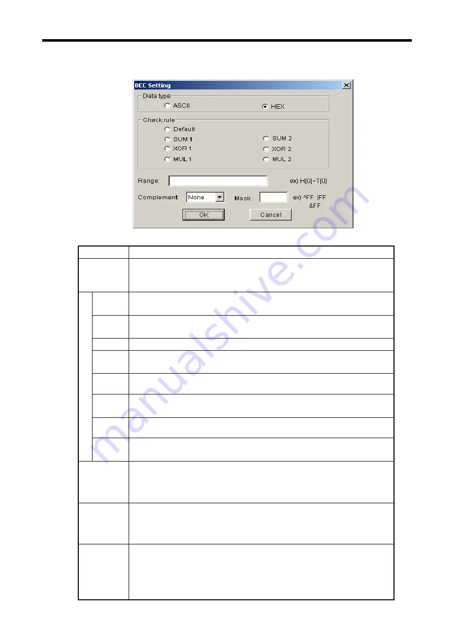
BCC setting: set BCC when it is needed.
Item Contents
Data Type
ASCII adds 2 bytes BCC value in ASCII type to frame. Hex adds 1 byte BCC value in Hex type to
frame. For the detailed setting BCC, refer to 8.1.6 “Execution of Commands”.
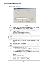
Default
It is that sum all the data from 2
nd
data to the data before the data marked as [BCC] and input the
result to the [BCC] area
LRC/CRC
Set as LRC/CRC check which is provided in modbus protocol.
For ASC communication set LRC, for HEX communication set CRC.
SUM 1
BCC method uses sum like defaults, but the user can set the BCC area.
SUM 2
BCC method is the same with SUM 1, but it’s used when the user masks any value to the last BCC
value.
XOR 1
BCC method is OR (Exclusive OR).
XOR 2
BCC method is the same with XOR 1, but it’s used when the user masks any value to the last BCC
value.
MUL 1
BCC method is MULTIPLY that is, multiplication.
Check Rule
MUL 2
BCC method is the same with MUL 1, but it’s used when the user masks any value to the last BCC
value.
Range
H signifies header, S is for segment, and T is for tail.
Ex1) When header is set as [ENQ][STX], tail is set as [EOT][ETX], and the range of setting
BCC is to be from [STX] to [ETX], then set as H [1]~T [1].
Complement
It is to set whether not to take complement number or to take the complement number of 1 or 2 at
[BCC] value. If mask setting is done after taking a complement number, the user can set any value to
do masking.
Mask
Sets any value and method of masking.
Ex1) When masking by XOR method, using a value, HFF : ^FF
Ex2) When masking by OR method, using a value, HFF : |FF
Ex3) When masking by AND method, using a value, HFF : &FF
Summary of Contents for GLOFA G7M-DR20U
Page 28: ...Chapter 4 Names of Parts 4 3 2 G7M DRT60U N 3 G7M DT60U N 4 G7M DT60U P...
Page 29: ...Chapter 4 Names of Parts 4 4 5 G7M DR60U DC 6 G7M DRT60U N DC 7 G7M DT60U N DC...
Page 31: ...Chapter 4 Names of Parts 4 6 3 G7M DT40U N 4 G7M DT40U P 5 G7M DR40U DC...
Page 32: ...Chapter 4 Names of Parts 4 7 6 G7M DRT40U N DC 7 G7M DT40U N DC 8 G7M DT40U P DC...
Page 33: ...Chapter 4 Names of Parts 4 8 4 1 3 30 point main unit 1 G7M DR30U 2 G7M DRT30U N 3 G7M DT30U N...
Page 34: ...Chapter 4 Names of Parts 4 9 4 G7M DT30U P 5 G7M DR30U DC 6 G7M DRT30U N DC...
Page 36: ...Chapter 4 Names of Parts 4 11 2 G7M DRT20U N 3 G7M DT20U N 4 G7M DT20U P...
Page 37: ...Chapter 4 Names of Parts 4 12 5 G7M DR20U DC 6 G7M DRT20U N DC 7 G7M DT20U N DC...
Page 38: ...Chapter 4 Names of Parts 4 13 8 G7M DT20U P DC...
Page 159: ...Chapter 7 Usage of Various Functions 7 52 c Program...
Page 183: ...Chapter 7 Usage of Various Functions 7 76 c Program...
Page 253: ...Chapter 8 Communication Functions 8 27 b When uses Ch 1 Built in RS 485...
Page 356: ...Appendix 1 System Definitions App1 9 6 Position Parameter...
Page 357: ...Appendix 1 System Definitions App1 10 7 High Speed Counter Parameter...


