


Chapter 8. Communication Functions
8-49
⑥
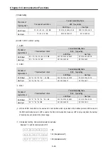
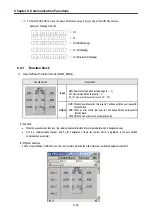
For SUM2,XOR2,MUL2, mask the above SUM check value (1 byte) and get the SUM Check value.
Example> Masking D3 as FF
1 1 0 1 0 0 1 1
1 1 0 1 0 0 1 1
1 1 1 1 1 1 1 1
0 0 1 0 1 1 0 0
8.2.3
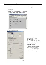
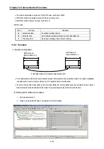
Function block
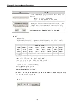
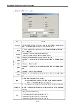
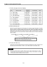
1) User defined function block (SND_MSG)
Function block
Description
Input
REQ: Execute function block at rising edge (0
→
1)
CH: Set communication channel (0 ~ 1)
FL_ID:
Frame list field number to send.
(0 ~ 15)
Output
NDR: When ends without error, this is set to 1 and keeps till the next request for
function block.
ERR: When an error occurs, this is set to 1 and keeps till the next request for
function block.
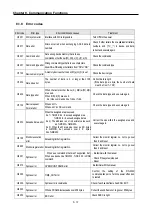
STATUS: When an error occurs, output error code.
(1) Function
•
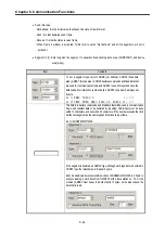
When the execution condition is on, the communication starts with protocol at parameter which is designated early.
•
‘CH’ is a communication channel, and ‘FL_ID’ designates a frame list number which is registered in the user defined
communication parameter.
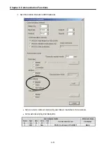
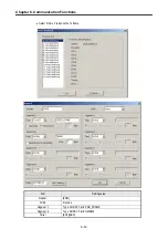
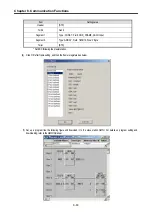
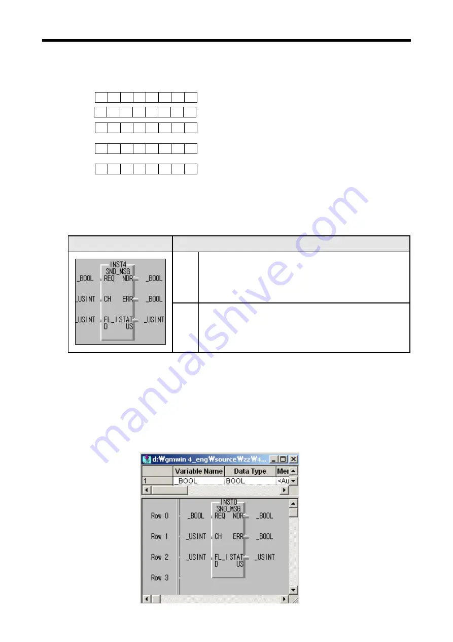
(2) Program example
•
When input condition (%MX000) is on, channel 1 starts communication with protocol at user defined parameter number 3.
1 1 1 1
1 1 1 1
= D3
= D3 (AND Masking)
= FF (OR Masking)
= 2C (Exclusive OR Masking)
= FF
Summary of Contents for GLOFA G7M-DR20U
Page 28: ...Chapter 4 Names of Parts 4 3 2 G7M DRT60U N 3 G7M DT60U N 4 G7M DT60U P...
Page 29: ...Chapter 4 Names of Parts 4 4 5 G7M DR60U DC 6 G7M DRT60U N DC 7 G7M DT60U N DC...
Page 31: ...Chapter 4 Names of Parts 4 6 3 G7M DT40U N 4 G7M DT40U P 5 G7M DR40U DC...
Page 32: ...Chapter 4 Names of Parts 4 7 6 G7M DRT40U N DC 7 G7M DT40U N DC 8 G7M DT40U P DC...
Page 33: ...Chapter 4 Names of Parts 4 8 4 1 3 30 point main unit 1 G7M DR30U 2 G7M DRT30U N 3 G7M DT30U N...
Page 34: ...Chapter 4 Names of Parts 4 9 4 G7M DT30U P 5 G7M DR30U DC 6 G7M DRT30U N DC...
Page 36: ...Chapter 4 Names of Parts 4 11 2 G7M DRT20U N 3 G7M DT20U N 4 G7M DT20U P...
Page 37: ...Chapter 4 Names of Parts 4 12 5 G7M DR20U DC 6 G7M DRT20U N DC 7 G7M DT20U N DC...
Page 38: ...Chapter 4 Names of Parts 4 13 8 G7M DT20U P DC...
Page 159: ...Chapter 7 Usage of Various Functions 7 52 c Program...
Page 183: ...Chapter 7 Usage of Various Functions 7 76 c Program...
Page 253: ...Chapter 8 Communication Functions 8 27 b When uses Ch 1 Built in RS 485...
Page 356: ...Appendix 1 System Definitions App1 9 6 Position Parameter...
Page 357: ...Appendix 1 System Definitions App1 10 7 High Speed Counter Parameter...


