


Chapter 8. Communication Function
8-62
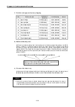
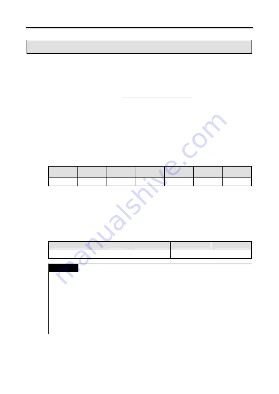
8.3 Modbus Protocol Communication
8.3.1 Introduction
GM7U built-in communication supports Modbus, the Modicon product’s communication protocol. It supports ASCII mode, using
ASCII (American Standard Code for Information Interchange) data and RTU (Remote Terminal Unit) mode using Hex data.
Function code used in Modbus is supported by function block and especially function code 01, 02, 03, 04, 05, 06, 15, and 16. Refer
to "Modicon Modbus Protocol Reference Guide"(
http://www.modicon.com/techpubs/toc7.html).
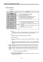
8.3.2 Basic specifications
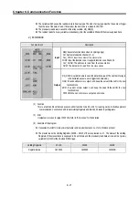
1) ASCII mode
(1)
It communicates, using ASCII data.
(2)
Each frame uses ': (colon: H3A)', for header, CRLF (Carriage Return-Line Feed: H0D H0A), for tail.
(3)
It allows Max. 1 second interval between characters.
(4)
It checks errors, using LRC.
(5)
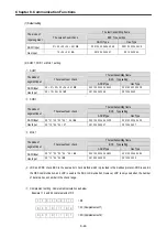
Frame structure (ASCII data)
Item
Header
Address
Function code
Data
LRC
Tail
(CR LF)
Size
1 byte
2 bytes
2 bytes
n bytes
2 bytes
2 bytes
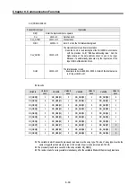
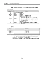
2) RTU mode
(1)
It communicates, using hex data.
(2)
There's no header and tail. It starts with address and finishes frame with CRC.
(3)
It has at least 3.5 character times between two frames.
(4)
It ignores the current frame when 1.5 character times elapse between characters.
(5)
It checks errors, using 16 bit CRC.
(6)
Frame structure (hex data).
Item
Address
Function code
Data
CRC
Size
1 byte
1 bytes
n bytes
2 bytes
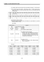
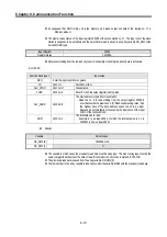
1)
The size constituting 1 letter is 1 character. So 1 character is 8 bits that is 1 byte.
2)
1 character time means the time lapsed for sending 1 character.
Ex) 1 character time calculation at 1200 bps
1200 bps means that it takes 1 sec to send 1200 bits. To send 1 bit, 1 sec/1200 bits = 0.83 ms. Therefore 1
character time is 0.83ms * 8 bits = 6.64ms.
3)
584, 984 A/B/X executes frame division, using intervals of more than 1 sec without LRC in processing internally.
REMARK
Summary of Contents for GLOFA G7M-DR20U
Page 28: ...Chapter 4 Names of Parts 4 3 2 G7M DRT60U N 3 G7M DT60U N 4 G7M DT60U P...
Page 29: ...Chapter 4 Names of Parts 4 4 5 G7M DR60U DC 6 G7M DRT60U N DC 7 G7M DT60U N DC...
Page 31: ...Chapter 4 Names of Parts 4 6 3 G7M DT40U N 4 G7M DT40U P 5 G7M DR40U DC...
Page 32: ...Chapter 4 Names of Parts 4 7 6 G7M DRT40U N DC 7 G7M DT40U N DC 8 G7M DT40U P DC...
Page 33: ...Chapter 4 Names of Parts 4 8 4 1 3 30 point main unit 1 G7M DR30U 2 G7M DRT30U N 3 G7M DT30U N...
Page 34: ...Chapter 4 Names of Parts 4 9 4 G7M DT30U P 5 G7M DR30U DC 6 G7M DRT30U N DC...
Page 36: ...Chapter 4 Names of Parts 4 11 2 G7M DRT20U N 3 G7M DT20U N 4 G7M DT20U P...
Page 37: ...Chapter 4 Names of Parts 4 12 5 G7M DR20U DC 6 G7M DRT20U N DC 7 G7M DT20U N DC...
Page 38: ...Chapter 4 Names of Parts 4 13 8 G7M DT20U P DC...
Page 159: ...Chapter 7 Usage of Various Functions 7 52 c Program...
Page 183: ...Chapter 7 Usage of Various Functions 7 76 c Program...
Page 253: ...Chapter 8 Communication Functions 8 27 b When uses Ch 1 Built in RS 485...
Page 356: ...Appendix 1 System Definitions App1 9 6 Position Parameter...
Page 357: ...Appendix 1 System Definitions App1 10 7 High Speed Counter Parameter...


