


Chapter 8. Communication Function
8-64
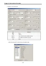
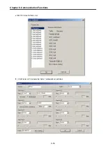
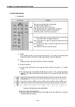
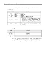
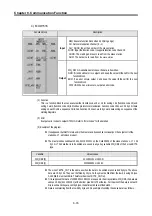
7)
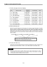
Function code types and memory mapping
Code
Function code name
Modicon PLC
Data address
GLOFA-mapping
Remark
01
Read Coil Status
0XXXX(bit-output)
%MX0~%MX9999
Read bits
02
Read Input Status
1XXXX(bit-input)
%MX0~%MX9999
Read bits
03
Read Holding Registers
4XXXX(word-output) %MW0~%MW9999
Read words
04
Read Input Registers
3XXXX(word-input) %MW0~%MW9999
Read words
05
Force Single Coil
0XXXX(bit-output)
%MX0~%MX9999
Write bit
06
Preset Single Register
4XXXX(word-output) %MW0~%MW9999
Write word
15
Force Multiple Coils
0XXXX(bit-output)
%MX0~%MX9999
Write bits
16
Preset Multiple Registers
4XXXX(word-output) %MW0~%MW9999
Write words
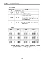
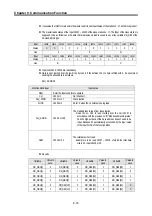
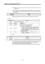
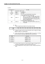
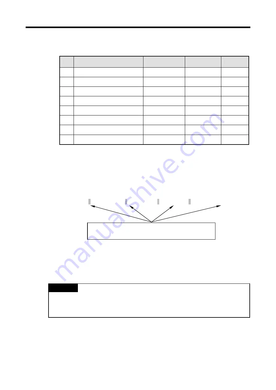
8) Modbus addressing rules
GM7U main unit starts its address from 0 and matches with 1 of Modicon products' data address. So GM7U's
address, n matches n+1 of Modicon products' address. Also, GM7U main unit has continuous M area without
any division of output contact points (0XXXX), input contact points (1XXXX), output registers (4XXXX), input
registers (3XXXX). This means that the output contact point 1 (0001) of Modicon products is marked as
communication address 0 and the input contact point 1 (0001) of Modicon products is marked as communication
address 0 in GM7U.
Output contact points (0XXXX), Input contact points (1XXXX), Output registers (4XXXX), Input registers (3XXXX)
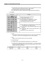
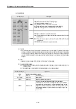
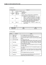
9)
The size of the data in use
As for data size, GM7U main unit supports 128 bytes in ASCII mode and 256 bytes in RTU mode. The maximum size of
the Modicon products is different from each other kind. So refer to "Modicon Modbus Protocol Reference Guide."
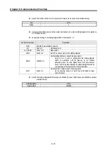
1)
GM7U main unit doesn't have any division between input and output area like Modicon PLC, when it
supports Modbus protocol communication. It uses only M area. So the user must be caution to in set input
and output area in M area for Modbus protocol communication.
REMARK
Highest data of data address dividing output contact point, input contact point,
output register, and input contact register in Modicon products.
Summary of Contents for GLOFA G7M-DR20U
Page 28: ...Chapter 4 Names of Parts 4 3 2 G7M DRT60U N 3 G7M DT60U N 4 G7M DT60U P...
Page 29: ...Chapter 4 Names of Parts 4 4 5 G7M DR60U DC 6 G7M DRT60U N DC 7 G7M DT60U N DC...
Page 31: ...Chapter 4 Names of Parts 4 6 3 G7M DT40U N 4 G7M DT40U P 5 G7M DR40U DC...
Page 32: ...Chapter 4 Names of Parts 4 7 6 G7M DRT40U N DC 7 G7M DT40U N DC 8 G7M DT40U P DC...
Page 33: ...Chapter 4 Names of Parts 4 8 4 1 3 30 point main unit 1 G7M DR30U 2 G7M DRT30U N 3 G7M DT30U N...
Page 34: ...Chapter 4 Names of Parts 4 9 4 G7M DT30U P 5 G7M DR30U DC 6 G7M DRT30U N DC...
Page 36: ...Chapter 4 Names of Parts 4 11 2 G7M DRT20U N 3 G7M DT20U N 4 G7M DT20U P...
Page 37: ...Chapter 4 Names of Parts 4 12 5 G7M DR20U DC 6 G7M DRT20U N DC 7 G7M DT20U N DC...
Page 38: ...Chapter 4 Names of Parts 4 13 8 G7M DT20U P DC...
Page 159: ...Chapter 7 Usage of Various Functions 7 52 c Program...
Page 183: ...Chapter 7 Usage of Various Functions 7 76 c Program...
Page 253: ...Chapter 8 Communication Functions 8 27 b When uses Ch 1 Built in RS 485...
Page 356: ...Appendix 1 System Definitions App1 9 6 Position Parameter...
Page 357: ...Appendix 1 System Definitions App1 10 7 High Speed Counter Parameter...


