


Chapter 8. Communication Function
8-75
z
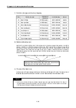
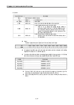
Result: The Coil 00173 turns ON. (In case of GM7U main unit, 1 is saved on the related M area.)
Coil
00173
Status 1
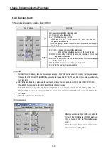
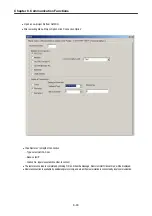
z
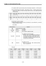
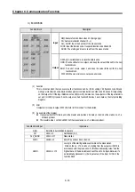
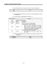
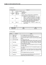
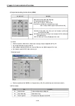
It assumes that GM7U main unit is the master and it writes on 1 word at Holding Register of the station no.
17, a Modicon product.
z
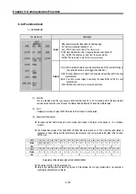
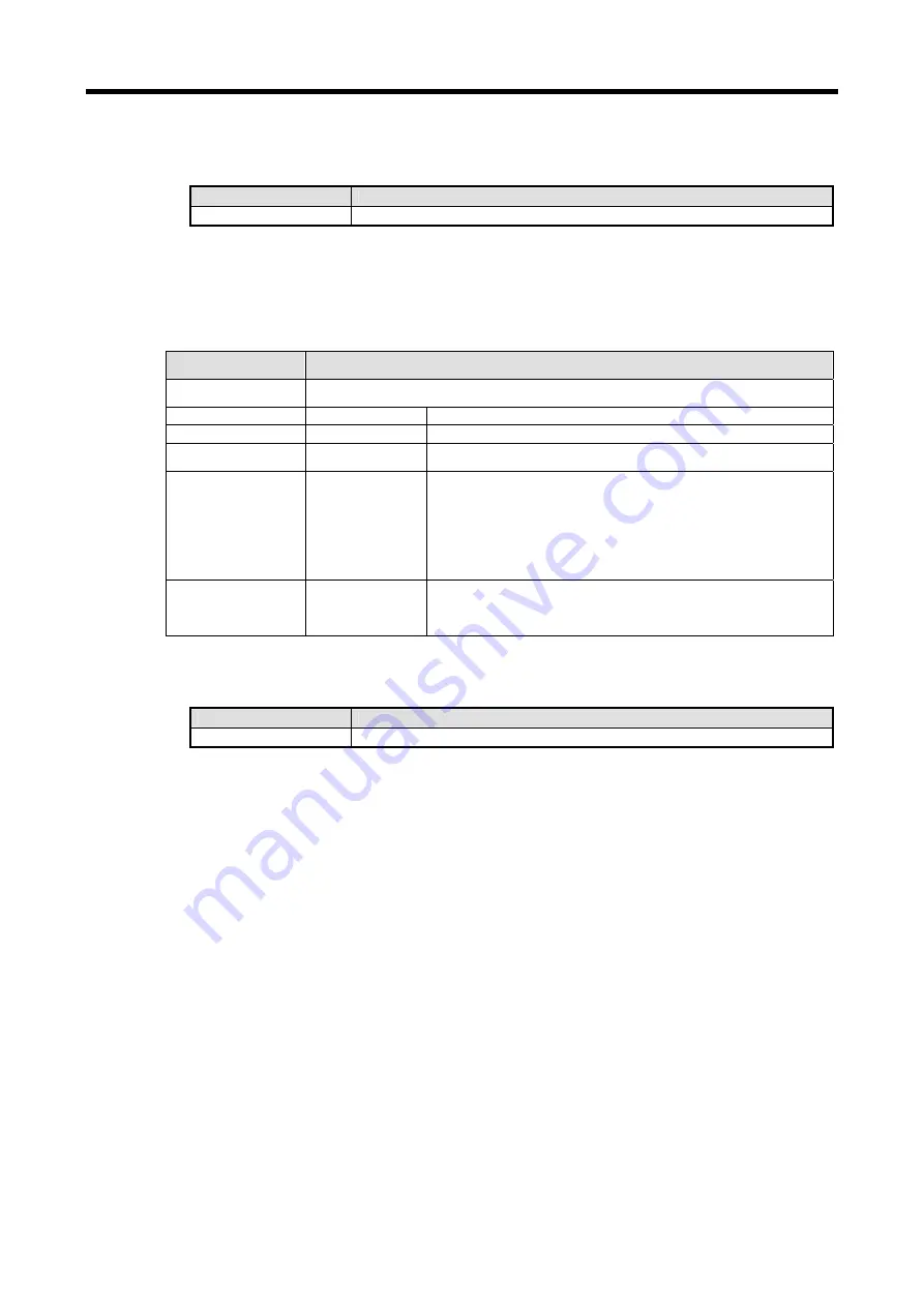
An example of writing 3 on Holding Register 4002 of the station no. 17.
Function block input
Input value
REQ
Enter the input condition to operate
CH
16#1 or 1
Set channel (0, 1)
SLV_ADDR
16#11 or 17
Slave station
FUNC
16#06 or 6
Enter ‘6’ as writes 1 word on the Holding Register.
ADDR
16#0001 or 1
Set the starting address to write on the slave station
-
Write on no. 1 to write on, starting from the Holding Register
40002 in accordance with the previous no. 8) “Modbus
addressing rules.” And the highest data of the data address
doesn’t need to be input. Because it’s automatically processed by
the input value of the input FUNC of the function block.
NUM
16#03 or 3
Set the number of data to write on the slave station..
-
As the example writes 3, of which hex is 16#0003. So input
16#03 for NUM
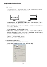
z
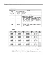
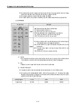
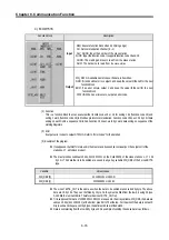
Result: The Holding Register 40002 is saved on 16#0003. (In case of GM7U main unit, 16#0003 is saved on
a related M area.)
Holding Register
40002
Register status
16#0003
Summary of Contents for GLOFA G7M-DR20U
Page 28: ...Chapter 4 Names of Parts 4 3 2 G7M DRT60U N 3 G7M DT60U N 4 G7M DT60U P...
Page 29: ...Chapter 4 Names of Parts 4 4 5 G7M DR60U DC 6 G7M DRT60U N DC 7 G7M DT60U N DC...
Page 31: ...Chapter 4 Names of Parts 4 6 3 G7M DT40U N 4 G7M DT40U P 5 G7M DR40U DC...
Page 32: ...Chapter 4 Names of Parts 4 7 6 G7M DRT40U N DC 7 G7M DT40U N DC 8 G7M DT40U P DC...
Page 33: ...Chapter 4 Names of Parts 4 8 4 1 3 30 point main unit 1 G7M DR30U 2 G7M DRT30U N 3 G7M DT30U N...
Page 34: ...Chapter 4 Names of Parts 4 9 4 G7M DT30U P 5 G7M DR30U DC 6 G7M DRT30U N DC...
Page 36: ...Chapter 4 Names of Parts 4 11 2 G7M DRT20U N 3 G7M DT20U N 4 G7M DT20U P...
Page 37: ...Chapter 4 Names of Parts 4 12 5 G7M DR20U DC 6 G7M DRT20U N DC 7 G7M DT20U N DC...
Page 38: ...Chapter 4 Names of Parts 4 13 8 G7M DT20U P DC...
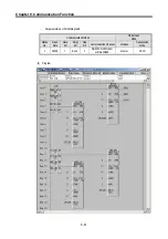
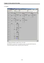
Page 159: ...Chapter 7 Usage of Various Functions 7 52 c Program...
Page 183: ...Chapter 7 Usage of Various Functions 7 76 c Program...
Page 253: ...Chapter 8 Communication Functions 8 27 b When uses Ch 1 Built in RS 485...
Page 356: ...Appendix 1 System Definitions App1 9 6 Position Parameter...
Page 357: ...Appendix 1 System Definitions App1 10 7 High Speed Counter Parameter...


