


Chapter 8. Communication Function
8-79
8.3.5 Example
According to the settings for the device supporting Modbus protocol, setting of GM7U basic unit is changed, but this example
explains Modbus protocol communication among GM7U units.
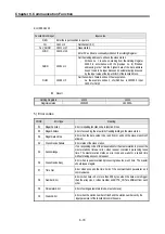
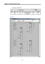
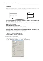
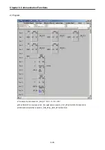
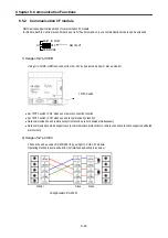
The slave station program: This outputs the received data saved in M area through the output coil.
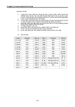
The master station program: It saves 16#FF (or 255) at %MW0 (It is coincided with %MX0 ~ MX15 or %MB0 ~ %MB1) in
function block MOD0506 (function code 06), then reads %MX0 through MOD0102 (function code 01), and again saves 0
at %MX0 ~ %MX9 using function block MOD1516 (function code 15), then reads %MW0 through Mod0304.
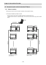
The cable used in this example is same with that used for the dedicated protocol communication between GM7U’s.
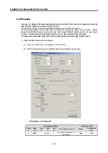
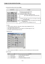
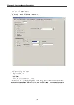
1) Slave station setting and a program
(1)
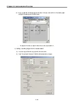
Open a new project file and a new program for the slave station.
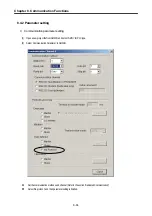
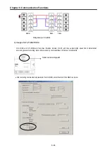
(2)
Select communication parameter in GMWIN parameter and the following window opens.
-
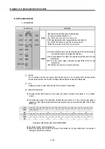
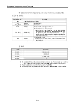
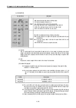
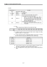
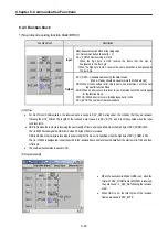
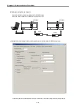
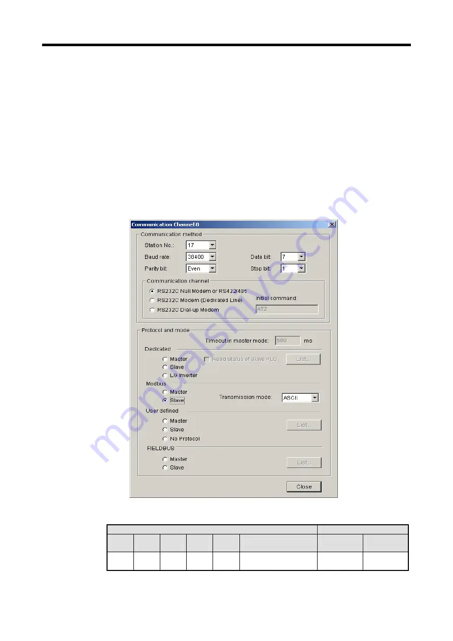
Set parameters as the following table.
Communication Method
Protocol and Mode
Station
No.
Baud
Rate
Data
Bit
Parity
Bit
Stop
Bit
Communication Channel
Modbus
Transmission
Mode
17 38400 7 Even 1
RS-232C Null Modem or
RS
-
422/485
Slave ASCII
Summary of Contents for GLOFA G7M-DR20U
Page 28: ...Chapter 4 Names of Parts 4 3 2 G7M DRT60U N 3 G7M DT60U N 4 G7M DT60U P...
Page 29: ...Chapter 4 Names of Parts 4 4 5 G7M DR60U DC 6 G7M DRT60U N DC 7 G7M DT60U N DC...
Page 31: ...Chapter 4 Names of Parts 4 6 3 G7M DT40U N 4 G7M DT40U P 5 G7M DR40U DC...
Page 32: ...Chapter 4 Names of Parts 4 7 6 G7M DRT40U N DC 7 G7M DT40U N DC 8 G7M DT40U P DC...
Page 33: ...Chapter 4 Names of Parts 4 8 4 1 3 30 point main unit 1 G7M DR30U 2 G7M DRT30U N 3 G7M DT30U N...
Page 34: ...Chapter 4 Names of Parts 4 9 4 G7M DT30U P 5 G7M DR30U DC 6 G7M DRT30U N DC...
Page 36: ...Chapter 4 Names of Parts 4 11 2 G7M DRT20U N 3 G7M DT20U N 4 G7M DT20U P...
Page 37: ...Chapter 4 Names of Parts 4 12 5 G7M DR20U DC 6 G7M DRT20U N DC 7 G7M DT20U N DC...
Page 38: ...Chapter 4 Names of Parts 4 13 8 G7M DT20U P DC...
Page 159: ...Chapter 7 Usage of Various Functions 7 52 c Program...
Page 183: ...Chapter 7 Usage of Various Functions 7 76 c Program...
Page 253: ...Chapter 8 Communication Functions 8 27 b When uses Ch 1 Built in RS 485...
Page 356: ...Appendix 1 System Definitions App1 9 6 Position Parameter...
Page 357: ...Appendix 1 System Definitions App1 10 7 High Speed Counter Parameter...


