


Chapter 9. Installation and Wiring
9-3
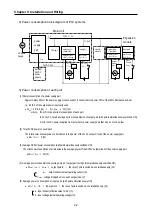
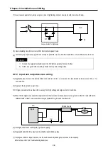
(6) Power consumption of the special module
•
W
S
= I
5V
X 5 + I
24V
X 24 (W)
(7) The sum of the above values is the power consumption of the entire PLC system.
•
W = W
PW
+ W
5V
+ W
24V
+ W
out
+ W
in
+ W
s
(W)
(8) Check the temperature rise within the control panel with calculation of that total power consumption(W).
The temperature rise in the control panel is expressed as:
T = W / UA [
°
C]
W : Power consumption of the entire PLC system(obtained as shown above)
A : Control panel inside surface area
[m
2
]
U : if the control panel temperature is controlled by a fan, etc
6
if control panel air is not circulated 4
9.1.2 Handling instructions
•
Do not drop off, and make sure that strong shock should not be applied.
•
Do not unload the PCB from its case. It can cause faults.
•
During wiring, be sure to check any foreign matter like wire scraps should not enter into the upper side of the PLC. If any
foreign matter has entered into it, always eliminate
it
.
1) Main unit or Expansion Module handling instructions
The followings explains instructions for handling or installing the Base unit or Expansion Module.
(1) I/O specifications re-check
Re-check the input voltage for the input part. if a voltage over the maximum switching capacity is applied, it can cause
faults, destruction or fire.
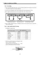
(2) Used wire
Select the wire with due consideration of ambient temperature and rated current. Its minimum specifications should be
AWG24(0.18
㎟
) or more.
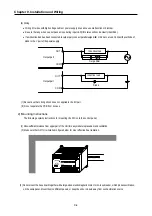
(3) Environment
When wiring the I/O part, if it locates near a device generating an cause short circuit, destruction or malfunction.
(4) Polarity
Before applying the power to part that has polarities, be sure to check its polarities.
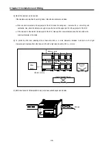
(5) Terminal block
Check its fixing. During drilling or wiring, do not allow any wire scraps to enter the PLC. It can cause malfunction and fault
.
Summary of Contents for GLOFA G7M-DR20U
Page 28: ...Chapter 4 Names of Parts 4 3 2 G7M DRT60U N 3 G7M DT60U N 4 G7M DT60U P...
Page 29: ...Chapter 4 Names of Parts 4 4 5 G7M DR60U DC 6 G7M DRT60U N DC 7 G7M DT60U N DC...
Page 31: ...Chapter 4 Names of Parts 4 6 3 G7M DT40U N 4 G7M DT40U P 5 G7M DR40U DC...
Page 32: ...Chapter 4 Names of Parts 4 7 6 G7M DRT40U N DC 7 G7M DT40U N DC 8 G7M DT40U P DC...
Page 33: ...Chapter 4 Names of Parts 4 8 4 1 3 30 point main unit 1 G7M DR30U 2 G7M DRT30U N 3 G7M DT30U N...
Page 34: ...Chapter 4 Names of Parts 4 9 4 G7M DT30U P 5 G7M DR30U DC 6 G7M DRT30U N DC...
Page 36: ...Chapter 4 Names of Parts 4 11 2 G7M DRT20U N 3 G7M DT20U N 4 G7M DT20U P...
Page 37: ...Chapter 4 Names of Parts 4 12 5 G7M DR20U DC 6 G7M DRT20U N DC 7 G7M DT20U N DC...
Page 38: ...Chapter 4 Names of Parts 4 13 8 G7M DT20U P DC...
Page 159: ...Chapter 7 Usage of Various Functions 7 52 c Program...
Page 183: ...Chapter 7 Usage of Various Functions 7 76 c Program...
Page 253: ...Chapter 8 Communication Functions 8 27 b When uses Ch 1 Built in RS 485...
Page 356: ...Appendix 1 System Definitions App1 9 6 Position Parameter...
Page 357: ...Appendix 1 System Definitions App1 10 7 High Speed Counter Parameter...


