
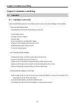


Chapter 9. Installation and Wiring
9-7
9.2 Wiring
The followings explains the wiring instructions for use of the system.
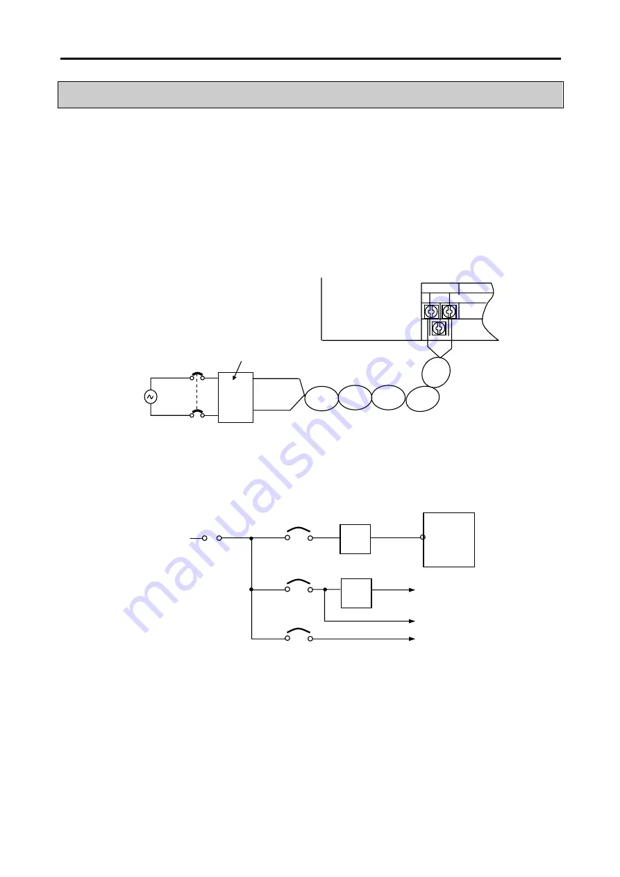
9.2.1 Power supply wiring
(1) When voltage fluctuations are larger than the specified value, connect a constant-voltage transformer
.
(2) Use a power supply which generates minimal noise across wire and across PLC and ground. (When excessive noise is
generated, connect an insulating transformer)
(3) Connect a power supply hat has less noise (if there are lots of noise, use insulated transformer).
(4)
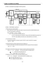
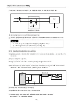
When wiring, separate the PLC power supply from those for I/O and power device as shown below.
※
T1,T2 : constant voltage transformer
(5)
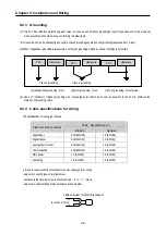
To minimize voltage drop, use the thickest (max. 2
㎟
) wires possible
(6) Do not bundle the 100 VAC and 24VDC cables with main-circuit (high voltage, large current) wires or the I/O signal wires.
If possible, provide more than 80
㎜
distance between the cables and wires.
AC100-240V
FG
GM7U
main unit
Constant-voltage transformer
T1
T2
PLC
Main power
AC220V
PLC power
I/O power
Main circuit
Main circuit device
I/O device
Summary of Contents for GLOFA G7M-DR20U
Page 28: ...Chapter 4 Names of Parts 4 3 2 G7M DRT60U N 3 G7M DT60U N 4 G7M DT60U P...
Page 29: ...Chapter 4 Names of Parts 4 4 5 G7M DR60U DC 6 G7M DRT60U N DC 7 G7M DT60U N DC...
Page 31: ...Chapter 4 Names of Parts 4 6 3 G7M DT40U N 4 G7M DT40U P 5 G7M DR40U DC...
Page 32: ...Chapter 4 Names of Parts 4 7 6 G7M DRT40U N DC 7 G7M DT40U N DC 8 G7M DT40U P DC...
Page 33: ...Chapter 4 Names of Parts 4 8 4 1 3 30 point main unit 1 G7M DR30U 2 G7M DRT30U N 3 G7M DT30U N...
Page 34: ...Chapter 4 Names of Parts 4 9 4 G7M DT30U P 5 G7M DR30U DC 6 G7M DRT30U N DC...
Page 36: ...Chapter 4 Names of Parts 4 11 2 G7M DRT20U N 3 G7M DT20U N 4 G7M DT20U P...
Page 37: ...Chapter 4 Names of Parts 4 12 5 G7M DR20U DC 6 G7M DRT20U N DC 7 G7M DT20U N DC...
Page 38: ...Chapter 4 Names of Parts 4 13 8 G7M DT20U P DC...
Page 159: ...Chapter 7 Usage of Various Functions 7 52 c Program...
Page 183: ...Chapter 7 Usage of Various Functions 7 76 c Program...
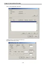
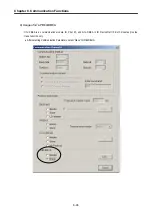
Page 253: ...Chapter 8 Communication Functions 8 27 b When uses Ch 1 Built in RS 485...
Page 356: ...Appendix 1 System Definitions App1 9 6 Position Parameter...
Page 357: ...Appendix 1 System Definitions App1 10 7 High Speed Counter Parameter...


