


Chapter 11. Troubleshooting
11-2
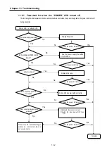
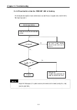
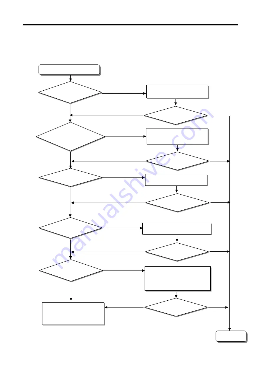
11.2.1 Flowchart for when the “POWER” LED turned off
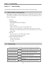
The following flowchart explains corrective action procedure used when the power is supplied or the power LED turns off
during operation.
Power LED is turned OFF
Is the power supply operating?
Is the voltage within the rated
power?
Is the fuse blown?
Is the power supply cable
connected?
Over current protection device
activated?
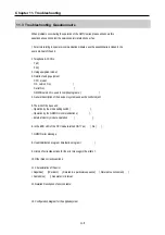
Write down the troubleshooting qu
estionnaire and contact the near
est service center
Supply the power.
Does the power LED turn on?
See the power supply be within
AC 110-240 V.
Replace the fuse.
Connect the power cable correctly.
Does the power LED turn on?
Does the power LED turn on?
Does the power LED turn on?
1)
Eliminate the excess current
2)
Switch the input power OFF then
ON
No
No
No
Yes
No
No
No
No
No
No
Yes
Yes
Yes
Yes
Yes
Yes
Yes
Yes
Complete
Yes
No
Does the power LED turn on?
Summary of Contents for GLOFA G7M-DR20U
Page 28: ...Chapter 4 Names of Parts 4 3 2 G7M DRT60U N 3 G7M DT60U N 4 G7M DT60U P...
Page 29: ...Chapter 4 Names of Parts 4 4 5 G7M DR60U DC 6 G7M DRT60U N DC 7 G7M DT60U N DC...
Page 31: ...Chapter 4 Names of Parts 4 6 3 G7M DT40U N 4 G7M DT40U P 5 G7M DR40U DC...
Page 32: ...Chapter 4 Names of Parts 4 7 6 G7M DRT40U N DC 7 G7M DT40U N DC 8 G7M DT40U P DC...
Page 33: ...Chapter 4 Names of Parts 4 8 4 1 3 30 point main unit 1 G7M DR30U 2 G7M DRT30U N 3 G7M DT30U N...
Page 34: ...Chapter 4 Names of Parts 4 9 4 G7M DT30U P 5 G7M DR30U DC 6 G7M DRT30U N DC...
Page 36: ...Chapter 4 Names of Parts 4 11 2 G7M DRT20U N 3 G7M DT20U N 4 G7M DT20U P...
Page 37: ...Chapter 4 Names of Parts 4 12 5 G7M DR20U DC 6 G7M DRT20U N DC 7 G7M DT20U N DC...
Page 38: ...Chapter 4 Names of Parts 4 13 8 G7M DT20U P DC...
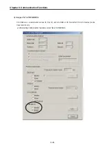
Page 159: ...Chapter 7 Usage of Various Functions 7 52 c Program...
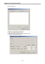
Page 183: ...Chapter 7 Usage of Various Functions 7 76 c Program...
Page 253: ...Chapter 8 Communication Functions 8 27 b When uses Ch 1 Built in RS 485...
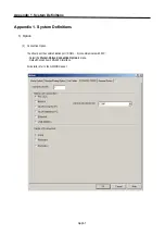
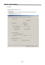
Page 356: ...Appendix 1 System Definitions App1 9 6 Position Parameter...
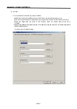
Page 357: ...Appendix 1 System Definitions App1 10 7 High Speed Counter Parameter...


