


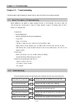


Chapter 11. Troubleshooting
11-
9
~
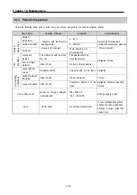
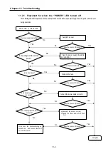
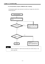
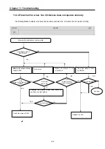
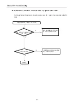
11.4 Troubleshooting Examples
Possible troubles with various circuits and their corrective actions are explained.
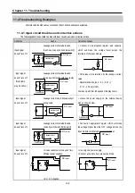
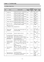
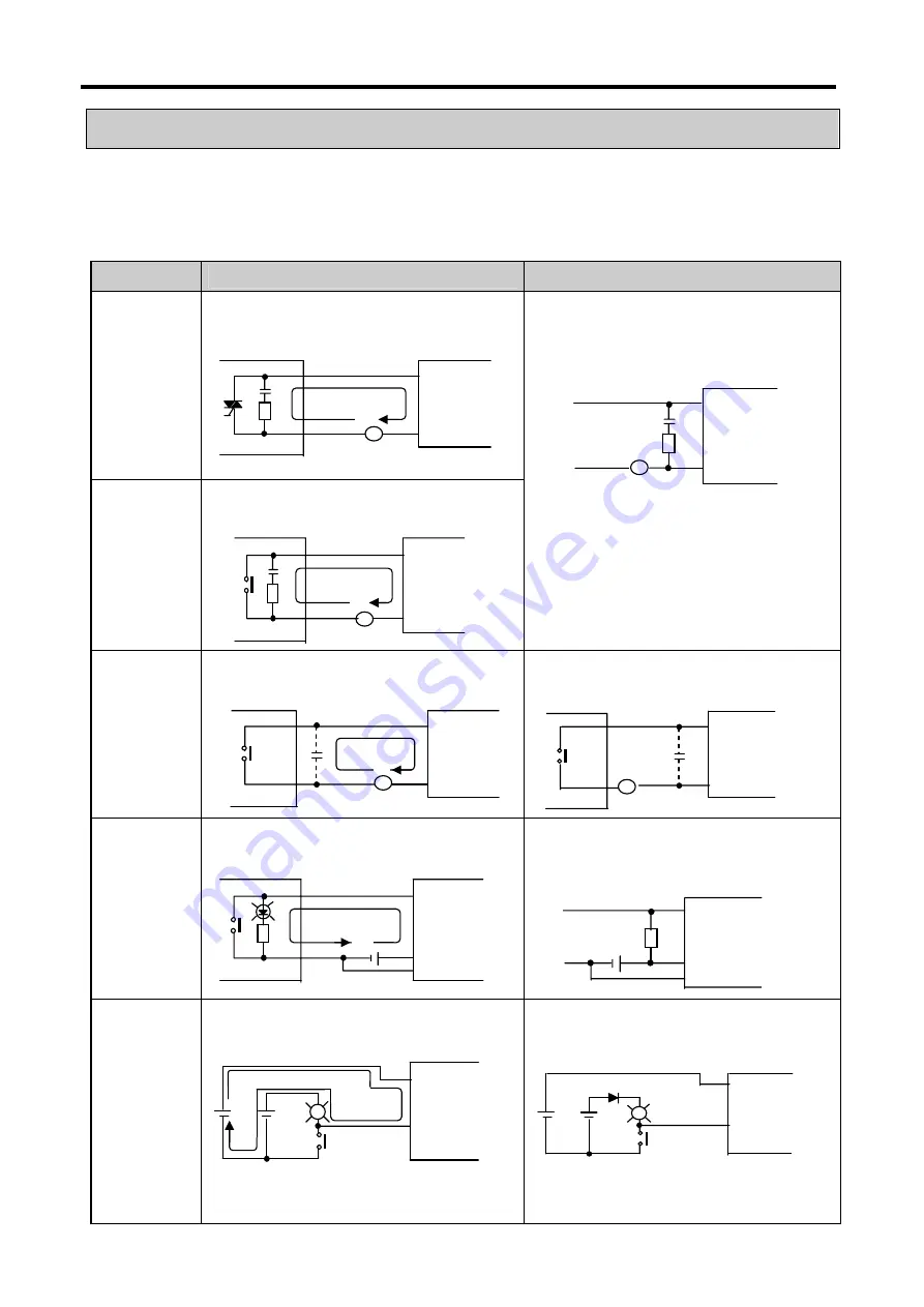
11.4.1 Input circuit troubles and corrective actions
The followings describe possible troubles with input circuits, as well as corrective actions.
Condition
Cause
Corrective Actions
Input signal
doesn’t turn off.
Leakage current of external device
(Such as a drive by non-contact switch)
Input signal
doesn’t turn off.
(Neon lamp
may be still on)
Leakage current of external device
(Drive by a limit switch with neon lamp)
y
Connect an appropriate register and capacity,
which will make the voltage lower across the
terminals of the input module.
y
CR values are determined by the leakage current
value.
−
Recommended value C : 0.1 ~ 0.47
㎌
R: 47 ~ 120
Ω
(1/2W)
Or make up another independent display circuit.
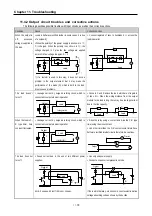
Input signal
doesn’t turn off.
Leakage current due to line capacity of
wiring cable.
y
Locate the power supply on the external device
side as shown below.
Input signal
doesn’t turn off.
Leakage current of external device
(Drive by switch with LED indicator)
y
Connect an appropriate register, which will make
the voltage higher than the OFF voltage across the
input module terminal and common terminal.
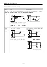
Input signal
doesn’t turn off.
y
Sneak current due to the use of two
different power supplies.
y
E1 > E2, sneaked.
y
Use only one power supply.
y
Connect a sneak current prevention diode.
DC
input
L
E1 E2
C
External device
AC
input
R
Leakage current
DC
input
R
E1
DC
input
L
E
External device
DC
input
R
Leakage current
C
AC
input
R
~
AC
input
External device
~
External device
AC
input
Leakage current
~
C
External device
AC
input
R
Leakage current
~
Summary of Contents for GLOFA G7M-DR20U
Page 28: ...Chapter 4 Names of Parts 4 3 2 G7M DRT60U N 3 G7M DT60U N 4 G7M DT60U P...
Page 29: ...Chapter 4 Names of Parts 4 4 5 G7M DR60U DC 6 G7M DRT60U N DC 7 G7M DT60U N DC...
Page 31: ...Chapter 4 Names of Parts 4 6 3 G7M DT40U N 4 G7M DT40U P 5 G7M DR40U DC...
Page 32: ...Chapter 4 Names of Parts 4 7 6 G7M DRT40U N DC 7 G7M DT40U N DC 8 G7M DT40U P DC...
Page 33: ...Chapter 4 Names of Parts 4 8 4 1 3 30 point main unit 1 G7M DR30U 2 G7M DRT30U N 3 G7M DT30U N...
Page 34: ...Chapter 4 Names of Parts 4 9 4 G7M DT30U P 5 G7M DR30U DC 6 G7M DRT30U N DC...
Page 36: ...Chapter 4 Names of Parts 4 11 2 G7M DRT20U N 3 G7M DT20U N 4 G7M DT20U P...
Page 37: ...Chapter 4 Names of Parts 4 12 5 G7M DR20U DC 6 G7M DRT20U N DC 7 G7M DT20U N DC...
Page 38: ...Chapter 4 Names of Parts 4 13 8 G7M DT20U P DC...
Page 159: ...Chapter 7 Usage of Various Functions 7 52 c Program...
Page 183: ...Chapter 7 Usage of Various Functions 7 76 c Program...
Page 253: ...Chapter 8 Communication Functions 8 27 b When uses Ch 1 Built in RS 485...
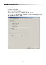
Page 356: ...Appendix 1 System Definitions App1 9 6 Position Parameter...
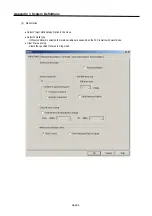
Page 357: ...Appendix 1 System Definitions App1 10 7 High Speed Counter Parameter...


