


Chapter 11. Troubleshooting
11
-
10
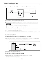
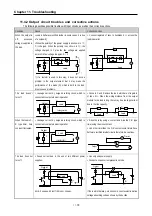
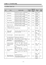
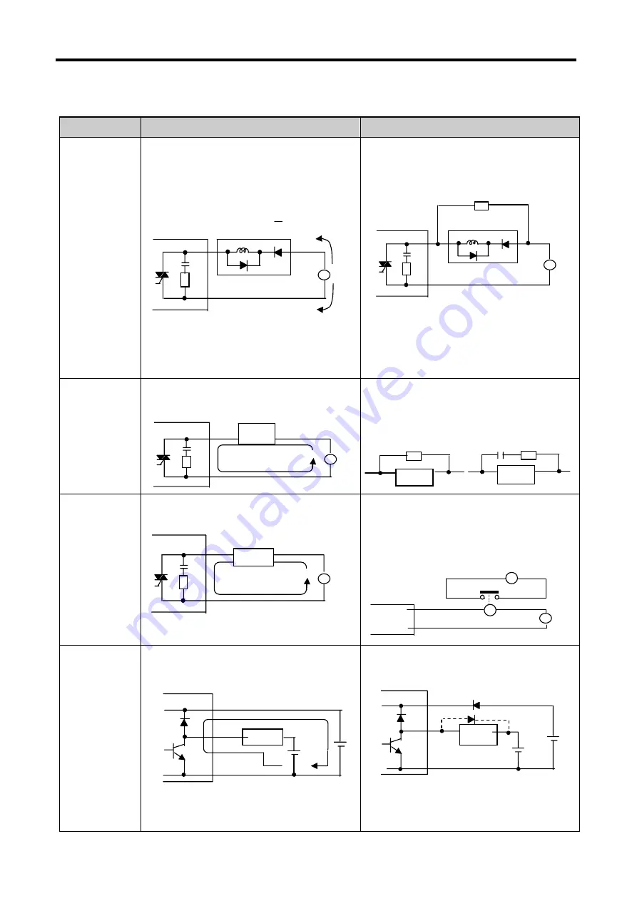
11.4.2 Output circuit troubles and corrective actions
The following describes possible troubles with input circuits, as well as their corrective actions.
Condition
Cause
Corrective Action
When the output is
off, excessive
voltage is applied to
the load.
y
Load is half-wave rectified inside (in some cases, it is true
of a solenoid)
y
When the polarity of the power supply is as shown in
①
,
C is charged. When the polarity is as shown in
②
, the
voltage charged in C plus the line voltage are applied
across D. Max. voltage is approx. 2
√
2.
*) If a resistor is used in this way, it does not pose a
problem to the output element. But it may make the
performance of the diode (D), which is built in the load,
drop to cause problems.
y
Connect registers of tens to hundreds K
Ω
across the
load in parallel.
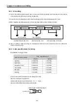
The load doesn’t
turn off.
y
Leakage current by surge absorbing circuit, which is
connected to output element in parallel.
y
Connect C and R across the load, which are of registers
of tens K
Ω
. When the wiring distance from the output
module to the load is long, there may be a leakage current
due to the line capacity.
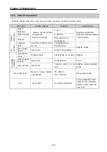
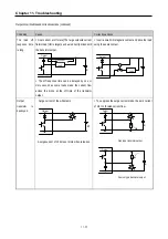
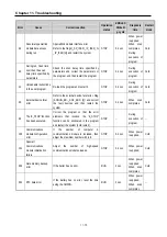
When the load is C-
R type timer, time
constant fluctuates.
y
Leakage current by surge absorbing circuit, which is
connected to output element in parallel.
y
Drive the relay using a contact and drive the C-R type
timer using the since contact.
y
Use other timer than the C
−
R contact some timers have
half-ware rectified internal circuits therefore, be cautious.
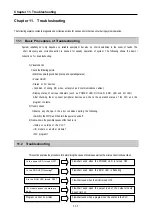
The load does not
turn off.
y
Sneak current due to the use of two different power
supplies.
E1<E2, sneaks. E1 is off (E2 is on), sneaks.
y
Use only one power supply.
y
Connect a sneak current prevention diode.
If the load is the relay, etc, connect a counter-electromotive
voltage absorbing code as shown by the dot line.
R
Load
R
Load
C
Output
Load
E
E
E1
Load
E
Output
C
R
Load
Leakage current
Output
~
C
R
Load
Leakage current
Output
~
X
T
Timer
Output
~
C
R
z
Load
D
~
C
R
Load
R
D
~
Summary of Contents for GLOFA G7M-DR20U
Page 28: ...Chapter 4 Names of Parts 4 3 2 G7M DRT60U N 3 G7M DT60U N 4 G7M DT60U P...
Page 29: ...Chapter 4 Names of Parts 4 4 5 G7M DR60U DC 6 G7M DRT60U N DC 7 G7M DT60U N DC...
Page 31: ...Chapter 4 Names of Parts 4 6 3 G7M DT40U N 4 G7M DT40U P 5 G7M DR40U DC...
Page 32: ...Chapter 4 Names of Parts 4 7 6 G7M DRT40U N DC 7 G7M DT40U N DC 8 G7M DT40U P DC...
Page 33: ...Chapter 4 Names of Parts 4 8 4 1 3 30 point main unit 1 G7M DR30U 2 G7M DRT30U N 3 G7M DT30U N...
Page 34: ...Chapter 4 Names of Parts 4 9 4 G7M DT30U P 5 G7M DR30U DC 6 G7M DRT30U N DC...
Page 36: ...Chapter 4 Names of Parts 4 11 2 G7M DRT20U N 3 G7M DT20U N 4 G7M DT20U P...
Page 37: ...Chapter 4 Names of Parts 4 12 5 G7M DR20U DC 6 G7M DRT20U N DC 7 G7M DT20U N DC...
Page 38: ...Chapter 4 Names of Parts 4 13 8 G7M DT20U P DC...
Page 159: ...Chapter 7 Usage of Various Functions 7 52 c Program...
Page 183: ...Chapter 7 Usage of Various Functions 7 76 c Program...
Page 253: ...Chapter 8 Communication Functions 8 27 b When uses Ch 1 Built in RS 485...
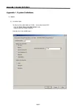
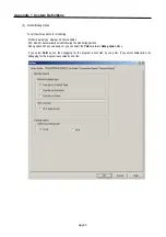
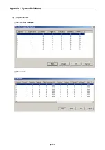
Page 356: ...Appendix 1 System Definitions App1 9 6 Position Parameter...
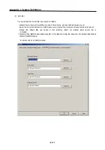
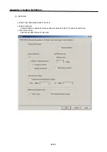
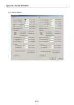
Page 357: ...Appendix 1 System Definitions App1 10 7 High Speed Counter Parameter...


