

Appendix 2. Flag Lists
App2-1
Appendix 2. Flag Lists
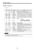
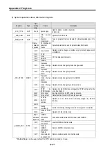
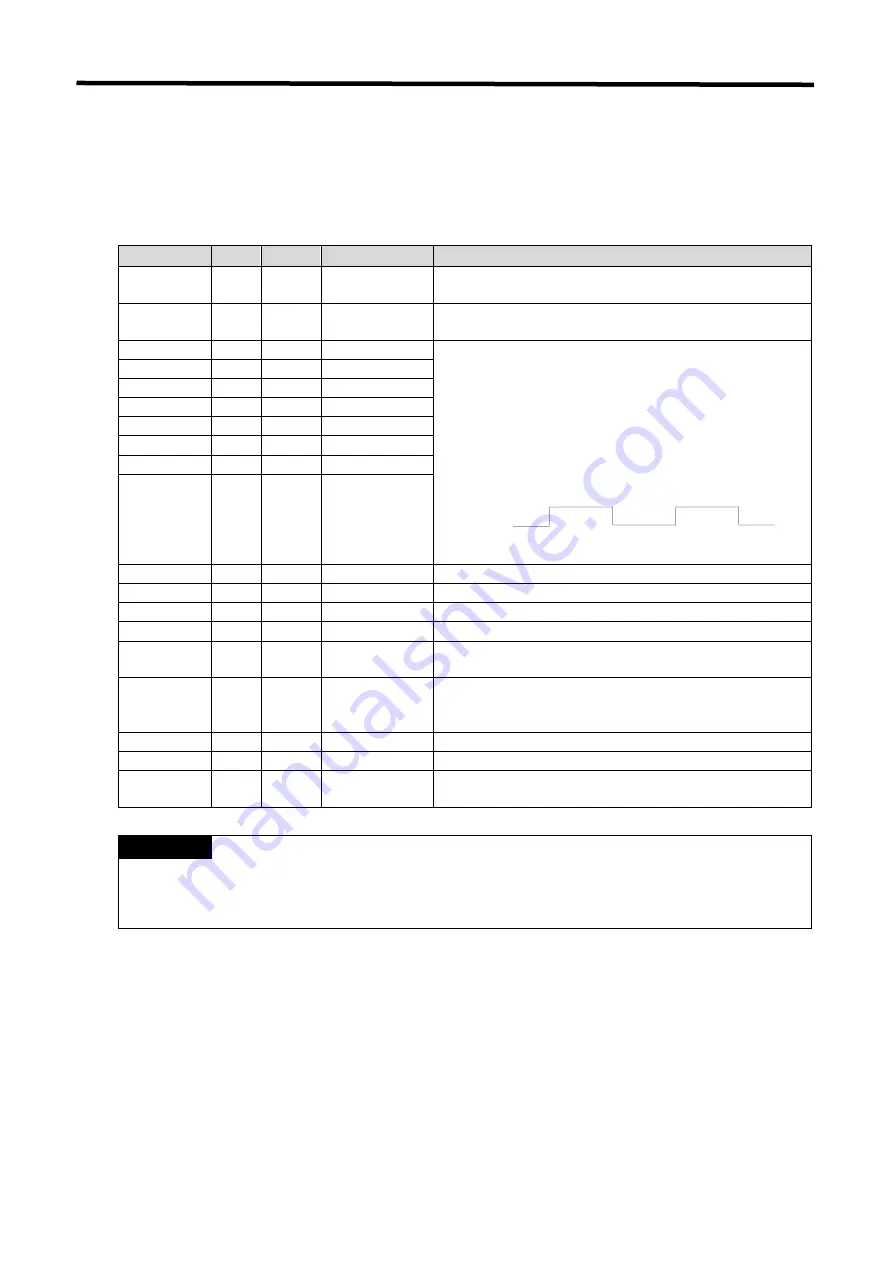
1) User flag lists
Keyword
Type
Write
Name
Description
_LER BOOL
Enable
Operation error
latch flag
Operation error latch flag by the program block(BP). Error
indication occurred while executing a program block
_ERR BOOL
Enable
Operation error
latch flag
Operation error flag by the operation function (FN) or function
block(FB). It is newly changed whenever an operation is executed.
_T20MS *
BOOL
−
20 ms Clock
_T100MS *
BOOL
−
100 ms Clock
_T200MS *
BOOL
−
200 ms Clock
_T1S *
BOOL
−
1s Clock
_T2S *
BOOL
−
2s Clock
_T10S *
BOOL
−
10s Clock
_T20S *
BOOL
−
20s clock
_T60S *
BOOL
−
60s Clock
These clock signals are used in the user programs, toggles on/off
every half cycle. The clock signal can be delayed or distorted in
accordance with program execution time as the signal toggles
after scan has been finished, therefore, it is recommended that
clock of enough longer than scan time be used. Clock signals
starts from Off when the initialization program or scan program
starts
•
Example: _T100MS clock
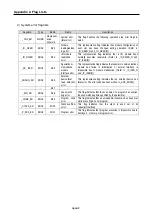
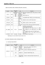
_ON *
BOOL
−
Always On
Usable in user programs.
_OFF *
BOOL
−
Always Off
Usable in user programs.
_1ON *
BOOL
−
First scan On
Turn On only during the first scan after the operation has started.
_1OFF *
BOOL
−
First scan Off
Turn Off only during the first scan after the operation has started.
_STOG *
BOOL
−
Scan Toggle
Toggles On/Off at every scan while a user program is being
executed. (On at the first scan)
_INT_DONE BOOL Enable
Initialization
Program
Complete
If this flag is set to on in the initialization program in an user
program, the initialization program stop its operation and the scan
program will starts.
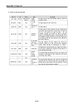
_INT_DATE DATE
−
RTC present date Date Data of standard format (Reference date – Jan. 1, 1984)
_RTC_TOD TOD
−
RTC present time Time Data( Reference time – 00:00:00)
_RTC_WEEK UNIT
−
RTC present day
Day data (0: Monday, 1:Thuesday, 2: Wednesday, 3: Thursday, 4:
Friday, 5: Saturday, 6:Sunday)
REMARK
1) Flags with the mark ‘*’ are initialized when the initialization program starts, and after its execution has been competed the
flags will change in accordance with the restart mode set.
2) RTC related flags could be used if only the optional module for RTC is installed.
50 ms
50 ms
Summary of Contents for GLOFA G7M-DR20U
Page 28: ...Chapter 4 Names of Parts 4 3 2 G7M DRT60U N 3 G7M DT60U N 4 G7M DT60U P...
Page 29: ...Chapter 4 Names of Parts 4 4 5 G7M DR60U DC 6 G7M DRT60U N DC 7 G7M DT60U N DC...
Page 31: ...Chapter 4 Names of Parts 4 6 3 G7M DT40U N 4 G7M DT40U P 5 G7M DR40U DC...
Page 32: ...Chapter 4 Names of Parts 4 7 6 G7M DRT40U N DC 7 G7M DT40U N DC 8 G7M DT40U P DC...
Page 33: ...Chapter 4 Names of Parts 4 8 4 1 3 30 point main unit 1 G7M DR30U 2 G7M DRT30U N 3 G7M DT30U N...
Page 34: ...Chapter 4 Names of Parts 4 9 4 G7M DT30U P 5 G7M DR30U DC 6 G7M DRT30U N DC...
Page 36: ...Chapter 4 Names of Parts 4 11 2 G7M DRT20U N 3 G7M DT20U N 4 G7M DT20U P...
Page 37: ...Chapter 4 Names of Parts 4 12 5 G7M DR20U DC 6 G7M DRT20U N DC 7 G7M DT20U N DC...
Page 38: ...Chapter 4 Names of Parts 4 13 8 G7M DT20U P DC...
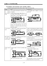
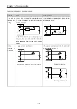
Page 159: ...Chapter 7 Usage of Various Functions 7 52 c Program...
Page 183: ...Chapter 7 Usage of Various Functions 7 76 c Program...
Page 253: ...Chapter 8 Communication Functions 8 27 b When uses Ch 1 Built in RS 485...
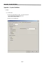
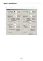
Page 356: ...Appendix 1 System Definitions App1 9 6 Position Parameter...
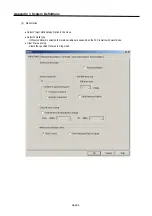
Page 357: ...Appendix 1 System Definitions App1 10 7 High Speed Counter Parameter...


