

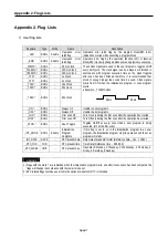
Appendix 2. Flag Lists
App2-4
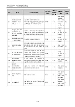
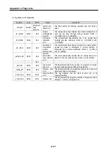
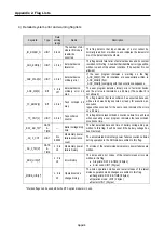
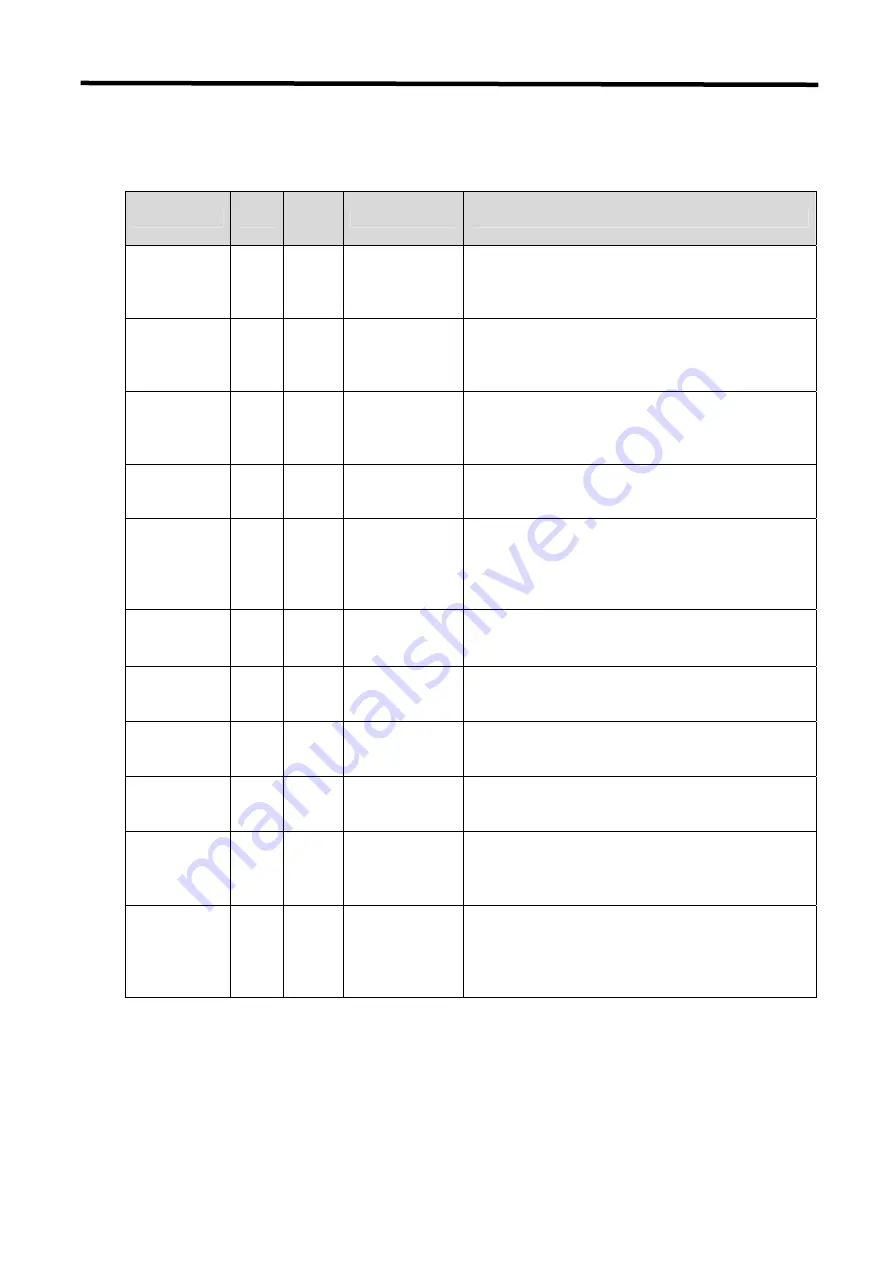
4) Detailed system error and warning flag lists
Keyword
Type
Data
setting
range
Name
Description
_IO_RWER_N UINT
0 to 15
The number of slot
where I/O module
read/write
occurred.
This flag detects that input modules of a slot cannot be
normally read from or written to, and indicates the lowest slot
No. of the detected slot numbers.
_ANC_ERR[n] UINT n: 0 to 7
External device
fatal error
This flag detects fatal error of external devices and its content
is written to this flag. A number that identifies error type will be
written to each of the sixteen locations. (The number 0 is not
allowed)
_ANC_WAR[n] UINT n: 0 to 7
External device
ordinary error
If the user program indicates a warning on the flag
_ANC_WB[n], the bit locations are sequentially written to
_ANC_WAR[n] from
_ANC_WAR[0] complying with their occurrence sequence.
_ANC_WB[n] BIT
n: 0 to
127
External device
ordinary error bit
map
The user program detects ordinary error of external device
and the errors are indicated on a bit map. (The number 0 is
not allowed)
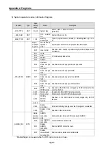
_TC_BMAP[n]
BIT
n: 0 to 7
Task collision bit
map
The flag detects that task collision has occurred because,
while a task was being executed or ready for execution, an
execution
request has occurred for the same task, indicates the errors
on a bit map.
_TC_CNT[n] UINT n: 0 to 7
Task collision
counter
This flag detects task collision occurrence time for each task
when executing a user program, indicates the task collision
occurrence time.
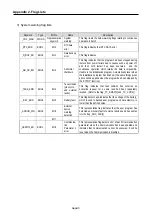
_BAT_ER_TM*
DATE
&
TIME
⎯
Batter voltage drop
time
The first detection date and time of battery voltage drop are
written to this flag. It will be reset if the battery voltage has
been restored.
_AC_F_CNT UINT
0 to
65535
Momentary power
failure occurrence
count
The accumulated momentary power failure occurrence times
during operation in the RUN mode is written to this flag.
_AC_F_TM[n]*
DATE
&
TIME
n: 0 to
15
Momentary power
failure history
The times of the latest sixteen momentary power failures are
written.
_ERR_HIS[n]*
n: 0 to
15
Error history
The times and error codes of the latest sixteen errors are
written to this flag.
•
Stop time: DATE & TIME (8 bytes)
•
Error code: UINT (2 bytes)
_MODE_HIS[n]*
n: 0 to
15
Operation mode
change history
The times, operation modes and restart modes of the latest
sixteen operation mode changes are written to this flag
•
Change time: DATE & TIME (8 bytes)
•
Operation mode: UINT (2 bytes)
•
Restart: UINT (2 bytes)
* Marked flags can be used while the RTC option module is in use.
Summary of Contents for GLOFA G7M-DR20U
Page 28: ...Chapter 4 Names of Parts 4 3 2 G7M DRT60U N 3 G7M DT60U N 4 G7M DT60U P...
Page 29: ...Chapter 4 Names of Parts 4 4 5 G7M DR60U DC 6 G7M DRT60U N DC 7 G7M DT60U N DC...
Page 31: ...Chapter 4 Names of Parts 4 6 3 G7M DT40U N 4 G7M DT40U P 5 G7M DR40U DC...
Page 32: ...Chapter 4 Names of Parts 4 7 6 G7M DRT40U N DC 7 G7M DT40U N DC 8 G7M DT40U P DC...
Page 33: ...Chapter 4 Names of Parts 4 8 4 1 3 30 point main unit 1 G7M DR30U 2 G7M DRT30U N 3 G7M DT30U N...
Page 34: ...Chapter 4 Names of Parts 4 9 4 G7M DT30U P 5 G7M DR30U DC 6 G7M DRT30U N DC...
Page 36: ...Chapter 4 Names of Parts 4 11 2 G7M DRT20U N 3 G7M DT20U N 4 G7M DT20U P...
Page 37: ...Chapter 4 Names of Parts 4 12 5 G7M DR20U DC 6 G7M DRT20U N DC 7 G7M DT20U N DC...
Page 38: ...Chapter 4 Names of Parts 4 13 8 G7M DT20U P DC...
Page 159: ...Chapter 7 Usage of Various Functions 7 52 c Program...
Page 183: ...Chapter 7 Usage of Various Functions 7 76 c Program...
Page 253: ...Chapter 8 Communication Functions 8 27 b When uses Ch 1 Built in RS 485...
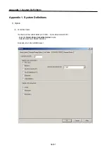
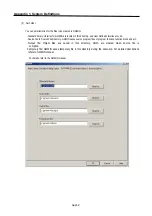
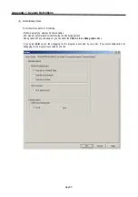
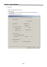
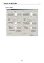
Page 356: ...Appendix 1 System Definitions App1 9 6 Position Parameter...
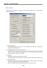
Page 357: ...Appendix 1 System Definitions App1 10 7 High Speed Counter Parameter...


