


Chapter 5. Power Supply / CPU
5-25
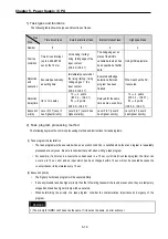
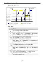
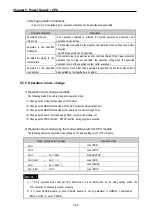
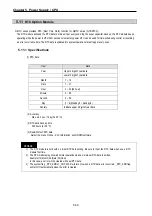
4) Debug operation conditions
• Two or more of the following four operation conditions can be simultaneously specified
Operation conditions
Description
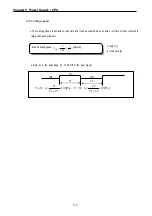
Executed by the one
(step over)
If an operation command is ordered, the system operates one operation unit
operation unit, and stops.
Executed to the specified
breakpoint
• If break step is specified in the program, the operation stops at those step, before
execution.
• Up to 8 break points can be specified.
Executed according to the
contact state
If the contact area to be watched and the condition (Read, Write, Value) where the
operation has to stop are specified, the operation stops when the specified
operation occurs at the specified contact. (after execution)
Executed by the specified
scan number
If the number of scan that will be operated is specified, the operation stops after it
has operated by the specified scan number.
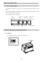
5.5.5 Operation mode change
1) Operation mode change methods
The following method is used to change the operation mode.
(1) Change by the mode-setting switch of CPU module.
(2) Change by the GMWIN connected with the CPU module communications port.
(3) Change by the GMWIN connected to the remote CPU module through Fnet.
(4) Change by the user’s command using FAM or computer link module, etc.
(5) Change by the STOP function’, ‘ESTOP function’ during program execution.
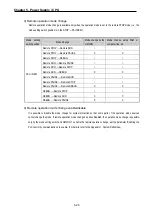
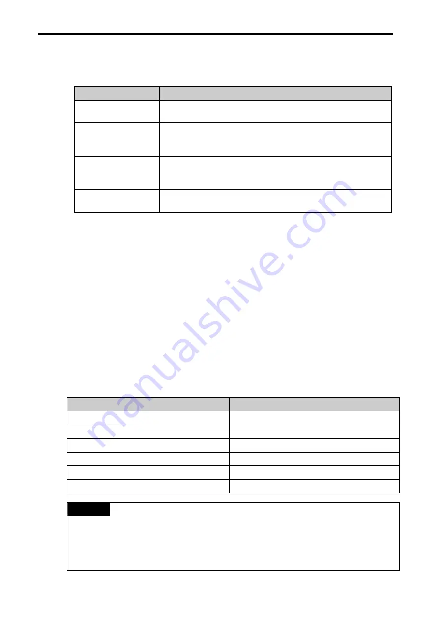
2) Operation mode change by the mode-setting switch of CPU module
The following shows the operation mode change by the mode-setting switch of CPU module.
Mode setting switch position
Operation mode
RUN
Local RUN
STOP
Local STOP
STOP
→
PAU / REM
Remote STOP
PAU / REM
→
RUN
∗
1
Local RUN
RUN
→
PAU / REM * 2
Local PAUSE
PAU / REM
→
STOP
Local STOP
REMARK
1)
∗
1: If the operation mode changes from RUN mode to local RUN mode by the mode setting switch, the
PLC operates continuously without stopping.
2) * 2: If Local PAUSE disable (or Local PAUSE enable) is set by parameter in GMWIN, it operated as
Remote RUN (or Local PAUSE).
Summary of Contents for GLOFA G7M-DR20U
Page 28: ...Chapter 4 Names of Parts 4 3 2 G7M DRT60U N 3 G7M DT60U N 4 G7M DT60U P...
Page 29: ...Chapter 4 Names of Parts 4 4 5 G7M DR60U DC 6 G7M DRT60U N DC 7 G7M DT60U N DC...
Page 31: ...Chapter 4 Names of Parts 4 6 3 G7M DT40U N 4 G7M DT40U P 5 G7M DR40U DC...
Page 32: ...Chapter 4 Names of Parts 4 7 6 G7M DRT40U N DC 7 G7M DT40U N DC 8 G7M DT40U P DC...
Page 33: ...Chapter 4 Names of Parts 4 8 4 1 3 30 point main unit 1 G7M DR30U 2 G7M DRT30U N 3 G7M DT30U N...
Page 34: ...Chapter 4 Names of Parts 4 9 4 G7M DT30U P 5 G7M DR30U DC 6 G7M DRT30U N DC...
Page 36: ...Chapter 4 Names of Parts 4 11 2 G7M DRT20U N 3 G7M DT20U N 4 G7M DT20U P...
Page 37: ...Chapter 4 Names of Parts 4 12 5 G7M DR20U DC 6 G7M DRT20U N DC 7 G7M DT20U N DC...
Page 38: ...Chapter 4 Names of Parts 4 13 8 G7M DT20U P DC...
Page 159: ...Chapter 7 Usage of Various Functions 7 52 c Program...
Page 183: ...Chapter 7 Usage of Various Functions 7 76 c Program...
Page 253: ...Chapter 8 Communication Functions 8 27 b When uses Ch 1 Built in RS 485...
Page 356: ...Appendix 1 System Definitions App1 9 6 Position Parameter...
Page 357: ...Appendix 1 System Definitions App1 10 7 High Speed Counter Parameter...


