


Chapter 5. Power Supply / CPU
5-27
5.6
Functions
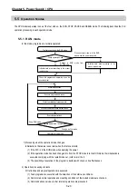
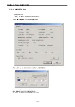
5.6.1 RESTART mode
The restart mode defines how to initialize variables and the system and how to operate in the RUN mode when the
system starts its operation with the RUN mode by re-application of the power or mode change. Two restart modes, cold
and warm restart are available and the execution condition for each restart mode is given below.
(For details, refer to the 4.5.1 Basic Parameters Edit’ of the GMWIN User’s Manual Section 4.5 Parameters Edit.)
1) Cold Restart
(1) It is executed when the restart mode parameter has been set to the cold restart mode.
(2) All data are cleared as ‘0’ and only variables of which initial value has been defined will be set as their initial value.
(3) Though the parameter has been set to the warm restart mode, cold restart will be executed at the first execution of a
program after it has been changed.
(4) In case of selection ‘Reset’ command in the GMWIN, it restarts in accordance with setting in parameter and in case of
selection ‘Overall Reset’ command; it restarts as cold restart mode.
2) Warm Restart
(1) It is executed when the restart mode parameter has been set to the warm restart mode.
(2) A data which set as retain & initial will be retain and a data which set as initial value will be set with default value during
the warm restart. All other data will be cleared with ‘0’.
(3) Though the parameter has been set to the warm restart mode, cold restart will be executed at the first execution of a
program after it has been stopped due to its down load and error.
(4) Though the parameter has been set to the warm restart mode, cold restart will be executed if data contents are
abnormal (i.e., the data does not remain at a power failure)
Summary of Contents for GLOFA G7M-DR20U
Page 28: ...Chapter 4 Names of Parts 4 3 2 G7M DRT60U N 3 G7M DT60U N 4 G7M DT60U P...
Page 29: ...Chapter 4 Names of Parts 4 4 5 G7M DR60U DC 6 G7M DRT60U N DC 7 G7M DT60U N DC...
Page 31: ...Chapter 4 Names of Parts 4 6 3 G7M DT40U N 4 G7M DT40U P 5 G7M DR40U DC...
Page 32: ...Chapter 4 Names of Parts 4 7 6 G7M DRT40U N DC 7 G7M DT40U N DC 8 G7M DT40U P DC...
Page 33: ...Chapter 4 Names of Parts 4 8 4 1 3 30 point main unit 1 G7M DR30U 2 G7M DRT30U N 3 G7M DT30U N...
Page 34: ...Chapter 4 Names of Parts 4 9 4 G7M DT30U P 5 G7M DR30U DC 6 G7M DRT30U N DC...
Page 36: ...Chapter 4 Names of Parts 4 11 2 G7M DRT20U N 3 G7M DT20U N 4 G7M DT20U P...
Page 37: ...Chapter 4 Names of Parts 4 12 5 G7M DR20U DC 6 G7M DRT20U N DC 7 G7M DT20U N DC...
Page 38: ...Chapter 4 Names of Parts 4 13 8 G7M DT20U P DC...
Page 159: ...Chapter 7 Usage of Various Functions 7 52 c Program...
Page 183: ...Chapter 7 Usage of Various Functions 7 76 c Program...
Page 253: ...Chapter 8 Communication Functions 8 27 b When uses Ch 1 Built in RS 485...
Page 356: ...Appendix 1 System Definitions App1 9 6 Position Parameter...
Page 357: ...Appendix 1 System Definitions App1 10 7 High Speed Counter Parameter...


