


Chapter 5. Power Supply / CPU
5-33
5.7
Memory Configuration
The CPU module includes two types of memory that are available by the user. One is program memory, which is used to store
the user programs written to implement a system by the user. The other is data memory, which stores data during operation.
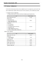
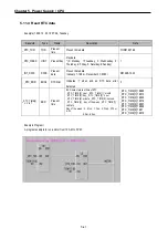
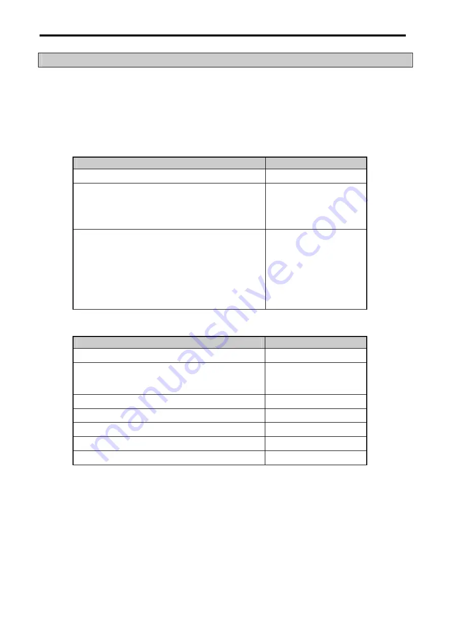
1) Program memory configuration
The table given below shows the contents to be stored and the storage capacity of program memory.
Item
Memory Capacity
Overall program memory area
132 kbyte
Parameter area
• Basic parameter area
• High speed link parameter area
• interrupt setting information area
7.8 kbyte
Program area
• Scan program area
• Task program area
• User defined function/function block area
• Standard library area
• Variable initialization information area
• Protective variable specification information area
124.2 kbyte
Data memory configuration
Item
Memory Capacity
Overall data memory area
44 kbyte
System area
• I/O information table
• Force I/O table
1 kbyte
System flag area
2 kbyte
Input image area
(%IX)
128 byte
Output image area
(%QX)
128 byte
Direct variable area
(%M)
10 kbyte
Symbolic variable area
30 kbyte
Summary of Contents for GLOFA G7M-DR20U
Page 28: ...Chapter 4 Names of Parts 4 3 2 G7M DRT60U N 3 G7M DT60U N 4 G7M DT60U P...
Page 29: ...Chapter 4 Names of Parts 4 4 5 G7M DR60U DC 6 G7M DRT60U N DC 7 G7M DT60U N DC...
Page 31: ...Chapter 4 Names of Parts 4 6 3 G7M DT40U N 4 G7M DT40U P 5 G7M DR40U DC...
Page 32: ...Chapter 4 Names of Parts 4 7 6 G7M DRT40U N DC 7 G7M DT40U N DC 8 G7M DT40U P DC...
Page 33: ...Chapter 4 Names of Parts 4 8 4 1 3 30 point main unit 1 G7M DR30U 2 G7M DRT30U N 3 G7M DT30U N...
Page 34: ...Chapter 4 Names of Parts 4 9 4 G7M DT30U P 5 G7M DR30U DC 6 G7M DRT30U N DC...
Page 36: ...Chapter 4 Names of Parts 4 11 2 G7M DRT20U N 3 G7M DT20U N 4 G7M DT20U P...
Page 37: ...Chapter 4 Names of Parts 4 12 5 G7M DR20U DC 6 G7M DRT20U N DC 7 G7M DT20U N DC...
Page 38: ...Chapter 4 Names of Parts 4 13 8 G7M DT20U P DC...
Page 159: ...Chapter 7 Usage of Various Functions 7 52 c Program...
Page 183: ...Chapter 7 Usage of Various Functions 7 76 c Program...
Page 253: ...Chapter 8 Communication Functions 8 27 b When uses Ch 1 Built in RS 485...
Page 356: ...Appendix 1 System Definitions App1 9 6 Position Parameter...
Page 357: ...Appendix 1 System Definitions App1 10 7 High Speed Counter Parameter...


