


iG5A
28
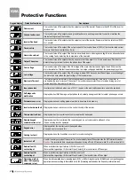
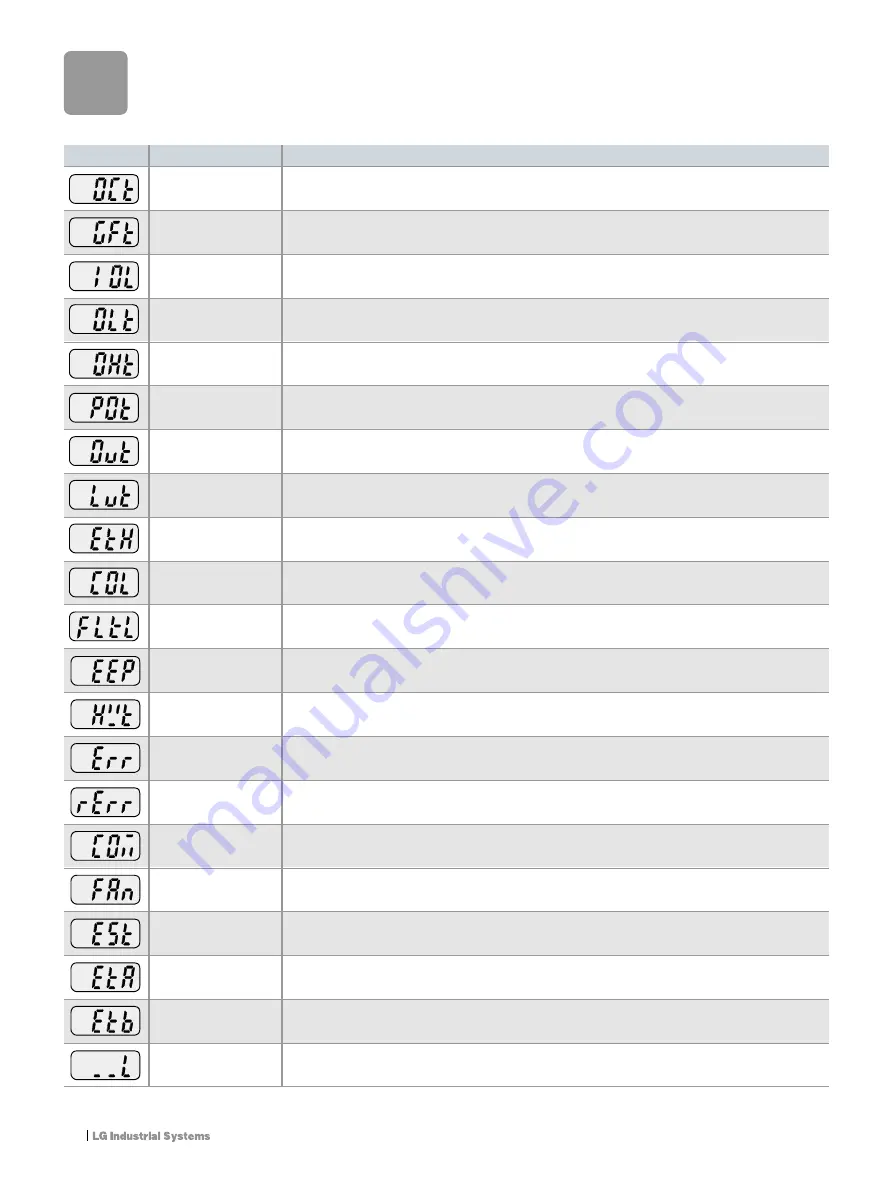
Protective Functions
Descriptions
Keypad display
The inverter turns off its output when the output current of the inverter flows more than 200% of the inverter
rated current.
The inverter turns off its output when a ground fault occurs and the ground fault current is more than the
internal setting value of the inverter.
The inverter turns off its output when the output current of the inverter flows more than the rated level (150%
for 1 minute).
The inverter turns off its output if the output current of the inverter flows at 150% of the inverter rated current
for more than the current limit time (1min).
The inverter turns off its output if the heat sink overheats due to a damaged cooling fan or an alien substance
in the cooling fan by detecting the temperature of the heat sink.
The inverter turns off its output when the one or more of the output (U, V, W) phase is open. The inverter
detects the output current to check the phase loss of the output.
The inverter turns off its output if the DC voltage of the main circuit increases higher than 400V when the
motor decelerates. This fault can also occur due to a surge voltage generated at the power supply system.
The inverter turns off its output if the DC voltage is below 180V because insufficient torque or overheating of
the motor can occur when the input voltage of the inverter drops.
The internal electronic thermal of the inverter determines the overheating of the motor. If the motor is
overloaded, the inverter turns off the output. The inverter cannot protect the motor when driving a motor
having more than 4 poles or multi motors.
Inverter output is blocked when one of R, S, T is open or the electrolytic capacitor needs to be replaced.
Displayed when IGBT damage, output phase short, output phase ground fault or output phase open occurs.
Displayed when user-setting parameters fails to be entered into memory.
Displayed when an error occurs in the control circuitry of the inverter.
Displayed when the inverter cannot communicate with the keypad.
Displayed when the inverter and the remote keypad do not communicate with each other.
It does not stop inverter operation.
Displayed after the inverter resets the keypad when
a keypad error occurs and this ....
Displayed when a fault condition occurs in the inverter cooling fan.
Used for the emergency stop of the inverter. The inverter instantly turns off the output when the EST terminal is turned on.
Caution:
The inverter starts to regular operation when turning off the EST terminal while FX or RX terminal is ON.
When multi-function input terminal (
I
20-
I
24) is set to 19
{External fault signal input A: (Normal Open Contact)}, the inverter turns off the output.
When multi-function input terminal (
I
20-
I
24) is set to 19
{External fault signal input B: (Normal Close Contact)}, the inverter turns off the output.
When inverter operation is set via analog input (0-10V or 0-20mA input) or option (RS-485) and no signal is applied,
operation is done according to the method set in
I
62 (Operating method when the frequency reference is lost).
Overcurrent
Ground fault current
Inverter Overload
Overload trip
Heat sink overheat
Output Phase loss
Over voltage
Low voltage
Electronic Thermal
Input phase loss
Self-diagnostic
malfunction
Parameter save error
Inverter hardware fault
Communication Error
Remote keypad
communication error
Keypad error
Cooling fan fault
Instant cut off
External fault A
contact input
External fault B
contact input
Operating method
when the frequency
command is lost
Protective functions
Summary of Contents for STARVERT iG5A
Page 30: ...iG5A 30 Memo...


